Page 4276 of 4770

(4)
(3)
(2)
B01159
ST±6
± STARTING (1MZ±FE)STARTER
1733 Author�: Date�:
DISASSEMBLY
1. REMOVE DUST PROTECTOR
2. REMOVE FIELD FRAME AND")
ST01W±01
B01156
B01157
ProtrusionIdentation
B01158
B01160
(1)
(4)
(3)
(2)
B01159
ST±6
± STARTING (1MZ±FE)STARTER
1733 Author�: Date�:
DISASSEMBLY
1. REMOVE DUST PROTECTOR
2. REMOVE FIELD FRAME AND ARMATURE
(a) Remove the nut, and disconnect the lead wire from the
magnetic switch terminal.
Torque: 5.9 N´m (60 kgf´cm, 52 in.´lbf)
(b) Remove the 2 through bolts.
Torque: 5.9 N´m (60 kgf´cm, 52 in.´lbf)
(c) Pull out the field frame together with the armature.
HINT:
Align the protrusion of the field frame with the groove of the
magnetic switch.
(d) Remove the O±ring from the field frame.
HINT:
At the time of installation, please refer to the following items.
Use a new O±ring.
3. REMOVE STARTER HOUSING, CLUTCH
ASSEMBLY AND GEAR
(a) Remove the 2 screws.
Torque: 5.9 N´m (60 kgf´cm, 52 in.´lbf)
(b) Remove these parts from the magnetic switch:
(1) Starter housing and clutch assembly
(2) Return spring
(3) Idler gear
(4) Bearing
4. REMOVE STEEL BALL
Using a magnetic finger, remove the steel ball from the clutch
shaft hole.
Page 4277 of 4770
B01161
P13528
± STARTING (1MZ±FE)STARTER
ST±7
1734 Author�: Date�:
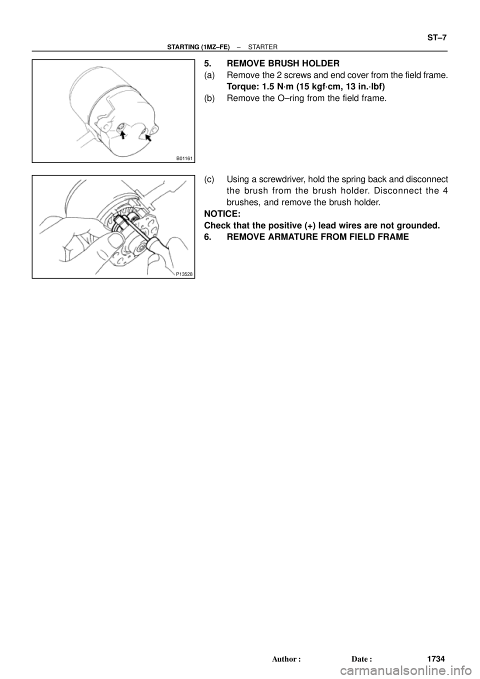
5. REMOVE BRUSH HOLDER
(a) Remove the 2 screws and end cover from the field frame.
Torque: 1.5 N´m (15 kgf´cm, 13 in.´lbf)
(b) Remove the O±ring from the field frame.
(c) Using a screwdriver, hold the spring back and disconnect
the brush from the brush holder. Disconnect the 4
brushes, and remove the brush holder.
NOTICE:
Check that the positive (+) lead wires are not grounded.
6. REMOVE ARMATURE FROM FIELD FRAME
Page 4286 of 4770
B01240
SST
B01241
ST±16
± STARTING (1MZ±FE)STARTER
1743 Author�: Date�: �
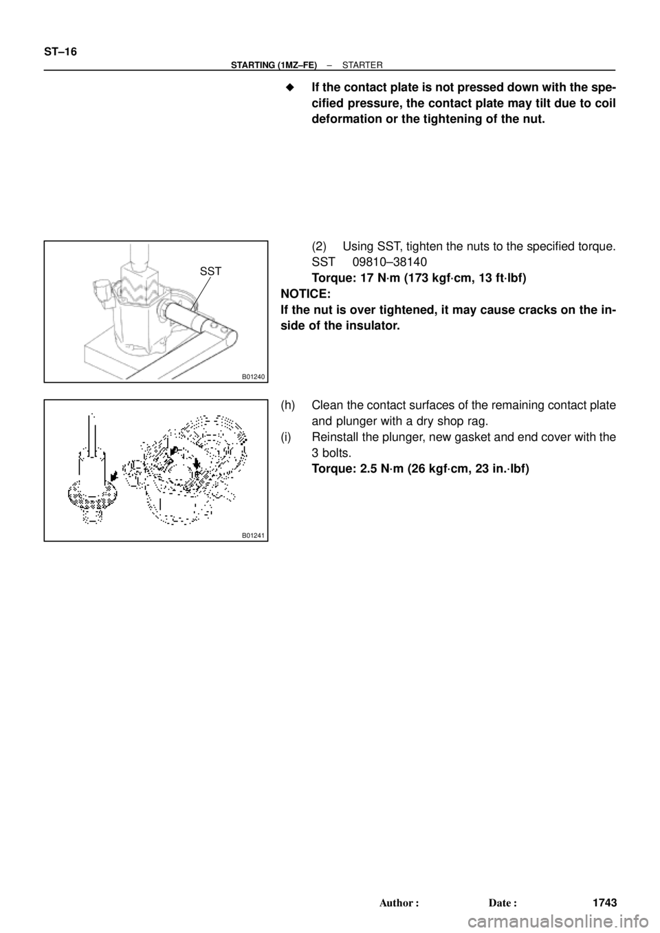
If the contact plate is not pressed down with the spe-
cified pressure, the contact plate may tilt due to coil
deformation or the tightening of the nut.
(2) Using SST, tighten the nuts to the specified torque.
SST 09810±38140
Torque: 17 N´m (173 kgf´cm, 13 ft´lbf)
NOTICE:
If the nut is over tightened, it may cause cracks on the in-
side of the insulator.
(h) Clean the contact surfaces of the remaining contact plate
and plunger with a dry shop rag.
(i) Reinstall the plunger, new gasket and end cover with the
3 bolts.
Torque: 2.5 N´m (26 kgf´cm, 23 in.´lbf)
Page 4298 of 4770
R07653
SR06G±01
F01477
SR±8
± STEERINGSTEERING WHEEL
2103 Author�: Date�:
STEERING WHEEL
INSPECTION
1. CHECK STEERING WHEEL FREEPLAY
With the vehicle stopped and tires facing straight ahead, rock
the steering wheel gently back and forth with light finger pres-
sure.
Freeplay should not exceed the maximum.
Maximum freeplay: 30 mm (1.18 in.)
2. CHECK STEERING EFFORT
(a) Center the steering wheel.
(b) Remove the steering wheel pad.
(See page SR±11)
(c) Start the engine and run it at idle.
(d) Measure the steering effort in both directions.
Reference: 5.9 N´m (60 kgf´cm, 52 in.´lbf)
HINT:
Be sure to consider the tire type, pressure and contact surface
before making your diagnosis.
(e) Torque the steering wheel set nut.
Torque: 35 N´m (360 kgf´cm, 26 ft´lbf)
(f) Install the steering wheel pad.
(See page SR±16)
Page 4299 of 4770
SR06H±03
W03348
Torx ScrewSteering Wheel Pad
Steering Wheel
Torx Screw
Steering Wheel Lower
No.2 Cover
Steering Column Assembly
Intermediate Shaft Assembly
No.1 Lower Instrument Panel Combination Switch
(w/ Spiral Cable)Steering Wheel Lower
No.2 Cover
Column
Upper Cover
Lower No.2
Cover
Column Lower Cover
Lower Instrument
Finish Panel
Hood Lock Control Cable
Clip
Front Door Inside Scuff Plate
Cowl Side Trim LH Lower
Instrument Panel
35 (360, 26)
25 (260, 19)
7.1 (72, 63 in.´lbf)
35 (360, 26)
35 (360, 26)
7.1 (72, 63 in.´lbf)
N´m (kgf´cm, ft´lbf) : Specified torque
± STEERINGTILT STEERING COLUMN
SR±9
2104 Author�: Date�:
TILT STEERING COLUMN
COMPONENTS
Page 4300 of 4770
F01476
Key Unlock Warning Switch
Column Upper Bracket Ignition Switch
Energy Absorbing PlateTransponder Key Coil Key Cylinder Lamp Assembly
Key
Interlock
Solenoid Key Cylinder
Transponder Key
Amplifier
Energy Absorbing Plate
Guide� Energy Absorbing Clip
Energy Absorbing Plate
Energy Absorbing Plate
Guide
� Energy Absorbing Clip Column TubeTilt Lever
Return Spring
� Tapered±Head Bolt Column Upper Tube Turn Signal Bracket
Lower Column Tube AttachmentColumn Tube Support
7 (70, 61 in.´lbf)
19 (195, 14)
N´m (kgf´cm, ft´lbf): Specified torque
� Non±reusable partw/ ENGINE IMMOBILISER SYSTEM:
A/T: SR±10
± STEERINGTILT STEERING COLUMN
2105 Author�: Date�:
Page 4305 of 4770
 Install the en")
SR06L±01
W03347
W03337
± STEERINGTILT STEERING COLUMN
SR±15
2110 Author�: Date�:
REASSEMBLY
NOTICE:
When using a vise, do not overtighten it.
1. INSTALL 2 ENERGY ABSORBING PLATES
(a) Install the energy absorbing plate guide and absorbing
plate.
(b) Install the new energy absorbing clip.
2. INSTALL COLUMN TUBE SUPPORT
(a) Install the tube attachment to the tube support.
(b) Torque the bolt and washer.
Torque: 19 N´m (195 kgf´cm, 14 ft´lbf)
3. INSTALL TILT LEVER RETURN SPRING
4. INSTALL TURN SIGNAL BRACKET
Torque the 2 bolts.
Torque: 7 N´m (70 kgf´cm, 61 in.´lbf)
5. INSTALL COLUMN UPPER BRACKET AND COLUMN
UPPER CLAMP
Tighten the 2 new tapered±head bolts until the bolt heads break
off.
6. w/ ENGINE EMMOBILISER SYSTEM:
INSTALL KEY CYLINDER LAMP ASSEMBLY
Install the lamp assembly to the key coil.
7. w/ ENGINE EMMOBILISER SYSTEM:
INSTALL TRANSPONDER KEY COIL WITH KEY CYL-
INDER LAMP ASSEMBLY
Tighten the screw.
8. w/o ENGINE EMMOBILISER SYSTEM:
INSTALL KEY CYLINDER LAMP ASSEMBLY
Tighten the screw.
Page 4306 of 4770
 Torque the 4 column assembly set nuts.
Torque:")
SR06M±01
W03303
Matchmarks
W02655
Mark SR±16
± STEERINGTILT STEERING COLUMN
2111 Author�: Date�:
INSTALLATION
1. INSTALL STEERING COLUMN ASSEMBLY
(a) Torque the 4 column assembly set nuts.
Torque: 25 N´m (260 kgf´cm, 19 ft´lbf)
(b) Connect the connectors.
2. INSTALL INTERMEDIATE SHAFT ASSEMBLY
Torque the bolt.
Torque: 35 N´m (360 kgf´cm, 26 ft´lbf)
3. CONNECT INTERMEDIATE SHAFT ASSEMBLY
(a) Align the matchmarks on the intermediate shaft and con-
trol valve shaft.
(b) Torque the bolt.
Torque: 35 N´m (360 kgf´cm, 26 ft´lbf)
4. INSTALL SPIRAL CABLE
(See page BE±23)
5. INSTALL COMBINATION SWITCH WITH SPIRAL
CABLE
(a) Tighten the 3 screws.
(b) Connect the airbag connector.
(c) Connect the 3 connectors.
6. INSTALL LOWER INSTRUMENT FINISH PANEL
7. INSTALL LH LOWER INSTRUMENT PANEL
Tighten the 4 bolts.
8. INSTALL No.1 LOWER INSTRUMENT PANEL
(a) Connect the hood lock control cable.
(b) Tighten the 2 screws.
9. INSTALL COWL SIDE TRIM
Install the clip.
10. INSTALL FRONT DOOR INSIDE SCUFF PLATE
11. INSTALL UPPER AND LOWER COLUMN COVERS
(a) Tighten the 3 screws.
(b) Install the lower No.2 cover to the lower cover.
12. CENTER SPIRAL CABLE
(a) Check that the front wheels are facing straight ahead.
(b) Turn the cable counterclockwise by hand until it becomes
harder to turn the cable.
(c) Then rotate the cable clockwise about 3 turns to align the
mark.
HINT:
The cable will rotate about 3 turns to either left or right of the
center.