Page 4169 of 4770
SF08N±03
S04740
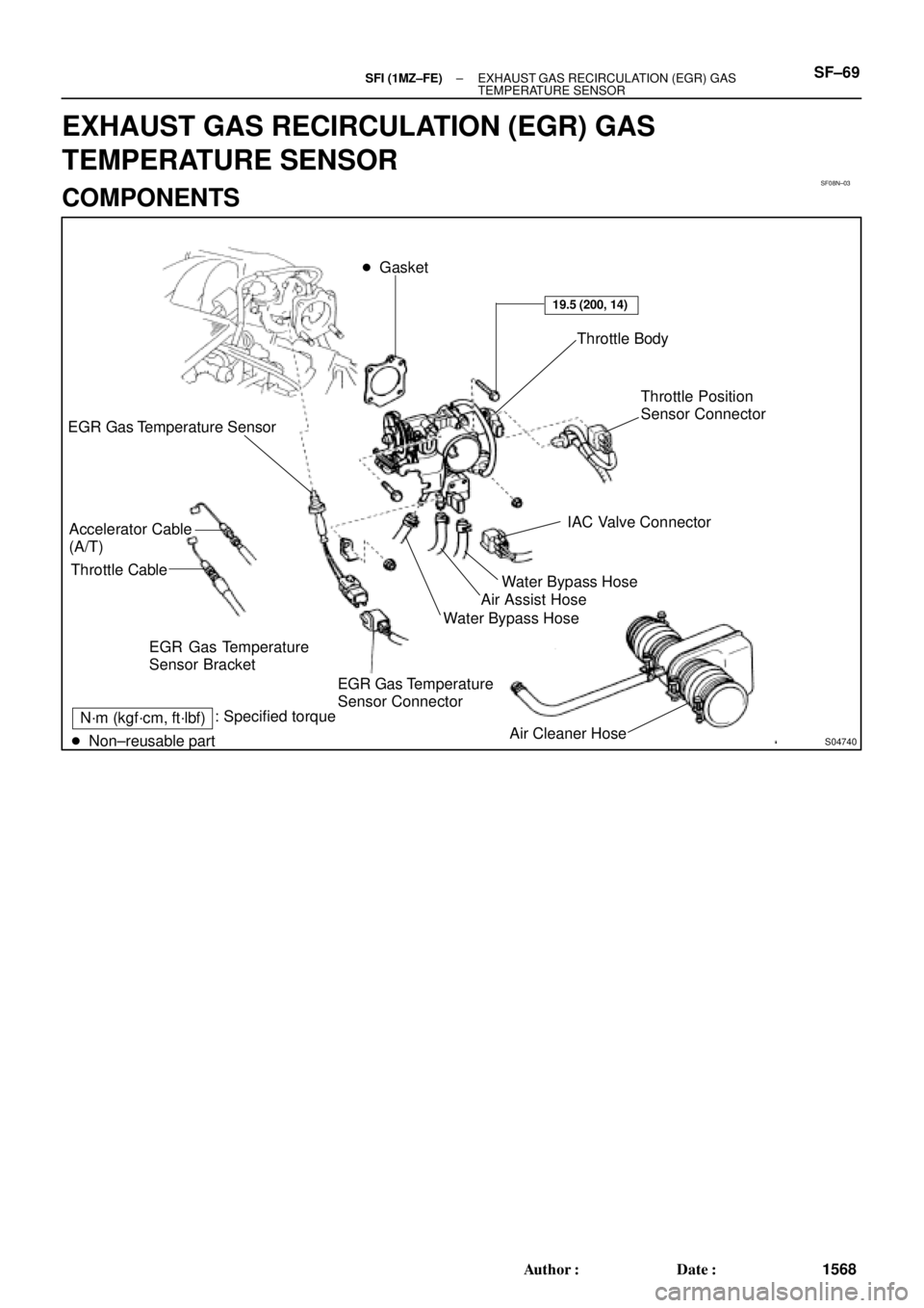
EGR Gas Temperature
Sensor Connector EGR Gas Temperature
Sensor Bracket
Air Cleaner Hose � Gasket
Throttle Body
Throttle Position
Sensor Connector
IAC Valve Connector
Water Bypass Hose
Air Assist Hose EGR Gas Temperature Sensor
Accelerator Cable
(A/T)
Throttle Cable
N´m (kgf´cm, ft´lbf): Specified torque
� Non±reusable partWater Bypass Hose
19.5 (200, 14)
± SFI (1MZ±FE)EXHAUST GAS RECIRCULATION (EGR) GAS
TEMPERATURE SENSORSF±69
1568 Author�: Date�:
EXHAUST GAS RECIRCULATION (EGR) GAS
TEMPERATURE SENSOR
COMPONENTS
Page 4171 of 4770
S05042
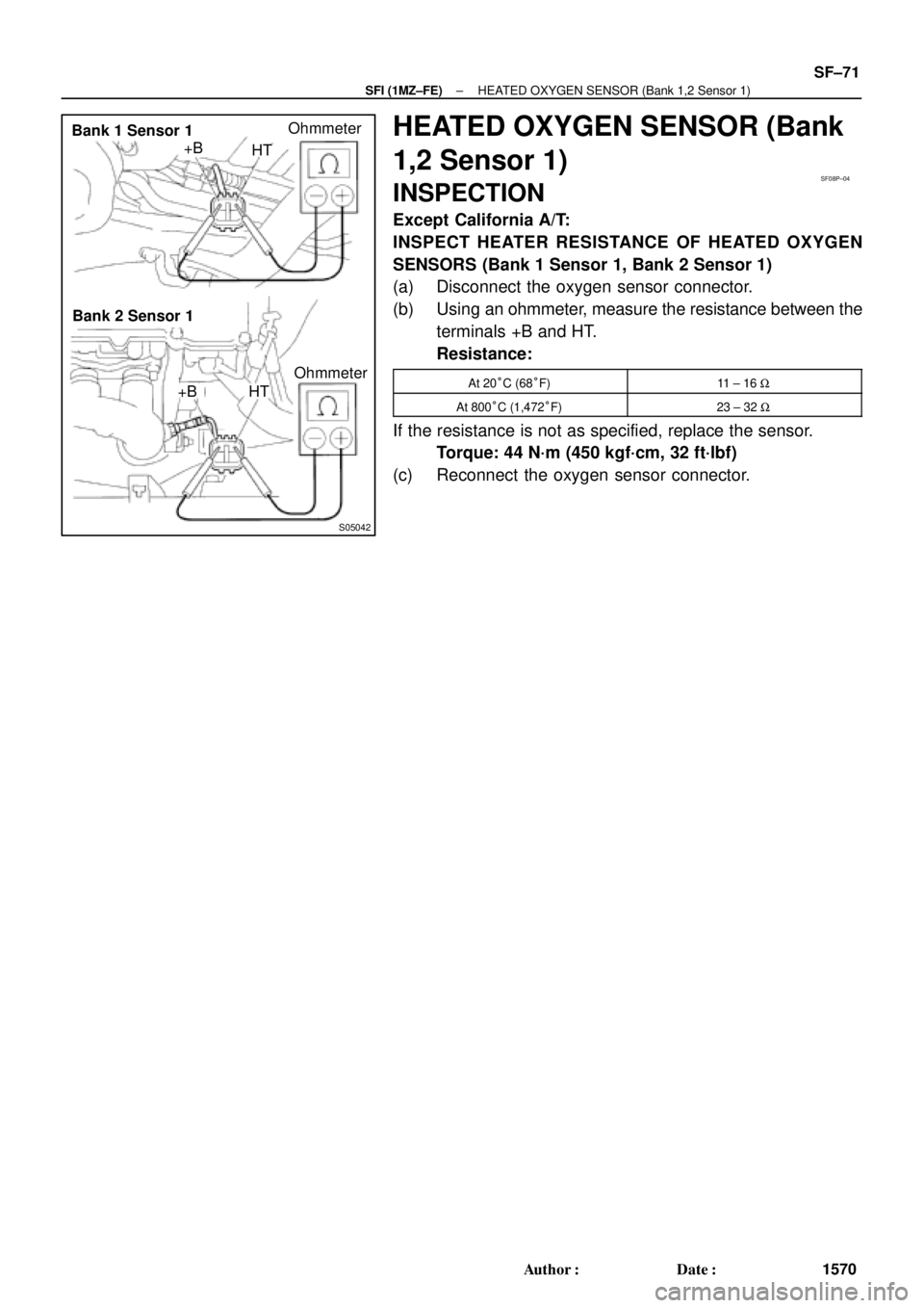
Bank 1 Sensor 1
Bank 2 Sensor 1+B
HTOhmmeter
+B HTOhmmeter
SF08P±04
± SFI (1MZ±FE)HEATED OXYGEN SENSOR (Bank 1,2 Sensor 1)
SF±71
1570 Author�: Date�:
HEATED OXYGEN SENSOR (Bank
1,2 Sensor 1)
INSPECTION
Except California A/T:
INSPECT HEATER RESISTANCE OF HEATED OXYGEN
SENSORS (Bank 1 Sensor 1, Bank 2 Sensor 1)
(a) Disconnect the oxygen sensor connector.
(b) Using an ohmmeter, measure the resistance between the
terminals +B and HT.
Resistance:
At 20°C (68°F)11 ± 16 W
At 800°C (1,472°F)23 ± 32 W
If the resistance is not as specified, replace the sensor.
Torque: 44 N´m (450 kgf´cm, 32 ft´lbf)
(c) Reconnect the oxygen sensor connector.
Page 4172 of 4770
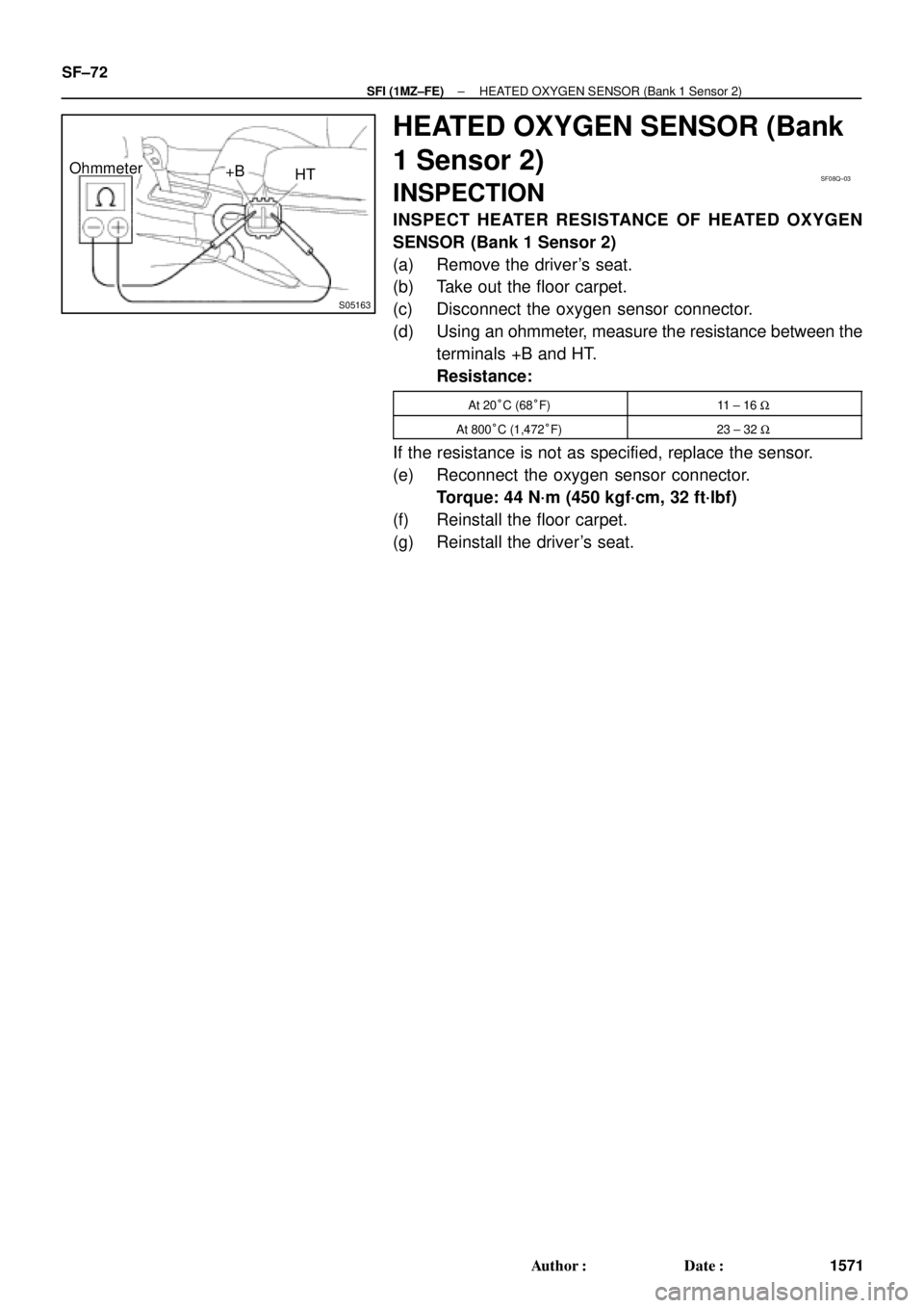
S05163
Ohmmeter
+B
HTSF08Q±03
SF±72
± SFI (1MZ±FE)HEATED OXYGEN SENSOR (Bank 1 Sensor 2)
1571 Author�: Date�:
HEATED OXYGEN SENSOR (Bank
1 Sensor 2)
INSPECTION
INSPECT HEATER RESISTANCE OF HEATED OXYGEN
SENSOR (Bank 1 Sensor 2)
(a) Remove the driver's seat.
(b) Take out the floor carpet.
(c) Disconnect the oxygen sensor connector.
(d) Using an ohmmeter, measure the resistance between the
terminals +B and HT.
Resistance:
At 20°C (68°F)11 ± 16 W
At 800°C (1,472°F)23 ± 32 W
If the resistance is not as specified, replace the sensor.
(e) Reconnect the oxygen sensor connector.
Torque: 44 N´m (450 kgf´cm, 32 ft´lbf)
(f) Reinstall the floor carpet.
(g) Reinstall the driver's seat.
Page 4189 of 4770
RS00Y±20
H03294
Column Upper Cover
Spiral CableSteering Wheel
Steering Wheel Pad
Column Lower Cover
N´m (kgf´cm, ft´lbf) : Specified torque
7.1 (72, 63 in.´lbf)
35 (360, 26)
Steering Wheel Lower
No.2 Cover
Steering Wheel Lower
No.2 Cover
Torx Screw
RS±14
± SUPPLEMENTAL RESTRAINT SYSTEMSTEERING WHEEL PAD AND SPIRAL CABLE
2159 Author�: Date�:
STEERING WHEEL PAD AND SPIRAL CABLE
COMPONENTS
Page 4202 of 4770
RS014±21
H08321
Front Passenger
Airbag Assembly
20 (205, 15)
N´m (kgf´cm, ft´lbf) : Specified torqueGlove Compartment Door
Finish PlateGlove Compartment Box
Cowl Side Trim RH
Front Door Scuff Plate RH
± SUPPLEMENTAL RESTRAINT SYSTEMFRONT PASSENGER AIRBAG ASSEMBLY
RS±27
2172 Author�: Date�:
FRONT PASSENGER AIRBAG ASSEMBLY
COMPONENTS
Page 4213 of 4770

RS019±05
W03509
H03288
RS±38
± SUPPLEMENTAL RESTRAINT SYSTEMFRONT PASSENGER AIRBAG ASSEMBLY
2183 Author�: Date�:
INSTALLATION
NOTICE:
Never use airbag parts from another vehicle. When replac-
ing parts, replace them with new parts.
HINT:
For step 2 to 4, refer to page BO±81.
1. INSTALL FRONT PASSENGER AIRBAG ASSEMBLY
(a) Install the front passenger airbag assembly with the 2
bolts.
Torque: 20 N´m (205 kgf´cm, 15 ft´lbf)
(b) Install the 4 nuts.
CAUTION:
�Make sure that no foreign objects are trapped be-
tween the airbag bag and the module.
�Do not damage the strap when installing the module.
NOTICE:
If the front passenger airbag assembly has been dropped,
or there are cracks, dents or other defects in the case or
connector, replace the front passenger airbag assembly
with a new one.
2. INSTALL GLOVE COMPARTMENT BOX
3. INSTALL COWL SIDE TRIM
4. INSTALL FRONT DOOR SCUFF PLATE
5. CONNECT AIRBAG CONNECTOR
(a) Connect the airbag connector.
(b) Put the connector on the glove compartment door finish
plate.
(c) Install the glove compartment door finish plate to the
glove compartment box.
Page 4214 of 4770
RS05G±02
H08245
Headrest
Headrest Support
Side Airbag
Assembly
Front Seatback Cover
Hinge Cover
Front Seat Cushion Shield
Release Handle
Power adjuster type:
Front Seat
Cushion Shield
Front Seat Cushion
Lower Shield Vartical Adjuster Knob Front Seat Cushion
Inner Shield
Front Seat Cushion
Lower Shield
37 (375, 27)
15 (150, 11)
18 (185, 13)
N´m (kgf´cm, ft´lbf): Specified torqueFront Seatback Assembly
Front Seat Cushion
Assembly
Seat Track Cover
± SUPPLEMENTAL RESTRAINT SYSTEMSIDE AIRBAG ASSEMBLY (TMC Made)
RS±39
2184 Author�: Date�:
SIDE AIRBAG ASSEMBLY (TMC Made)
COMPONENTS
Page 4224 of 4770

RS±49
2194 Author�: Date�:
INSTALLATION
NOTICE:
Never use airbag parts from another vehicle. When replac-
ing part")
RS0EV±01
H02259
A
B
± SUPPLEMENTAL RESTRAINT SYSTEMSIDE AIRBAG ASSEMBLY (TMC Made)
RS±49
2194 Author�: Date�:
INSTALLATION
NOTICE:
Never use airbag parts from another vehicle. When replac-
ing parts, replace them with new parts.
1. INSTALL SEATBACK ASSEMBLY
(a) Install the seatback assembly.
(b) Install new hog rings.
HINT:
Install the hog rings to prevent wrinkles as little as possible.
(c) Install the 4 bolts.
Torque:
Bolt A: 18 N´m (185 kgf´cm, 13 ft´lbf)
Bolt B: 15 N´m (150 kgf´cm, 11 ft´lbf)
2. INSTALL FRONT SEAT CUSHION INNER SHIELD
3. INSTALL FRONT SEAT CUSHION SHIELD
4. Manual adjuster type:
INSTALL VERTICAL ADJUSTER KNOB
5. Manual adjuster type:
INSTALL RELEASE HANDLE
6. Power adjuster type:
CONNECT CONNECTOR
Connect the connector to the power seat switch.
7. INSTALL FRONT SEAT CUSHION LOWER SHIELD
8. INSTALL HEADREST SUPPORT
9. INSTALL HEADREST
10. INSTALL FRONT SEAT
(a) Slide the front seat to the most front position.
NOTICE:
Make sure that seat adjuster locks.
(b) Without holding the seat track handle, mount the seat to
the vehicle.
HINT:
If holding the seat track handle, the adjusted most front position
will slip off.
(c) Power adjuster type:
Connect the side airbag connector and power seat con-
nector.
(d) Manual adjuster type:
Connect the side airbag connector.
(e) Tighten the bolts on the rear side temporarily, starting
from the bolt on the inner side tighten them completely.
Torque: 37 N´m (375 kgf´cm, 27 ft´lbf)
 : Specified torque
7.1 (72, 63 in.´lbf)
35 (360, 26)
Steering Wheel Lower")

N´m (kgf´cm, ft´lbf) : Specified torqueGlove Compartment Door
Finish PlateGlove Compartment Box
Cowl Side Trim RH
Front Door Scuff Pla")
