Page 4307 of 4770
W03304
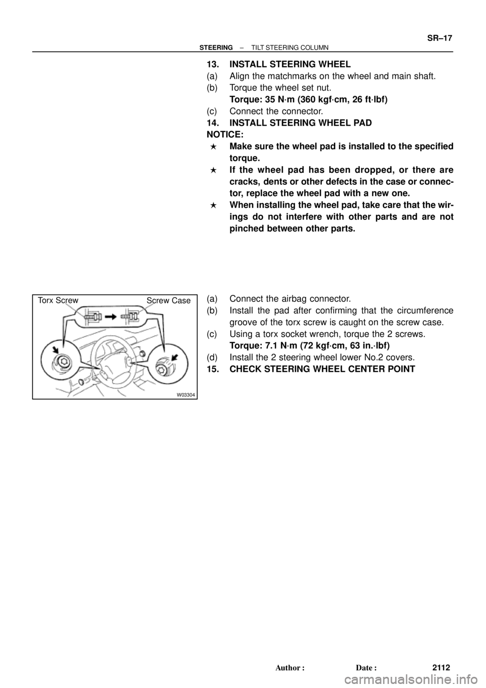
Torx Screw
Screw Case
± STEERINGTILT STEERING COLUMN
SR±17
2112 Author�: Date�:
13. INSTALL STEERING WHEEL
(a) Align the matchmarks on the wheel and main shaft.
(b) Torque the wheel set nut.
Torque: 35 N´m (360 kgf´cm, 26 ft´lbf)
(c) Connect the connector.
14. INSTALL STEERING WHEEL PAD
NOTICE:
�Make sure the wheel pad is installed to the specified
torque.
�If the wheel pad has been dropped, or there are
cracks, dents or other defects in the case or connec-
tor, replace the wheel pad with a new one.
�When installing the wheel pad, take care that the wir-
ings do not interfere with other parts and are not
pinched between other parts.
(a) Connect the airbag connector.
(b) Install the pad after confirming that the circumference
groove of the torx screw is caught on the screw case.
(c) Using a torx socket wrench, torque the 2 screws.
Torque: 7.1 N´m (72 kgf´cm, 63 in.´lbf)
(d) Install the 2 steering wheel lower No.2 covers.
15. CHECK STEERING WHEEL CENTER POINT
Page 4308 of 4770
SR06N±03
W03364
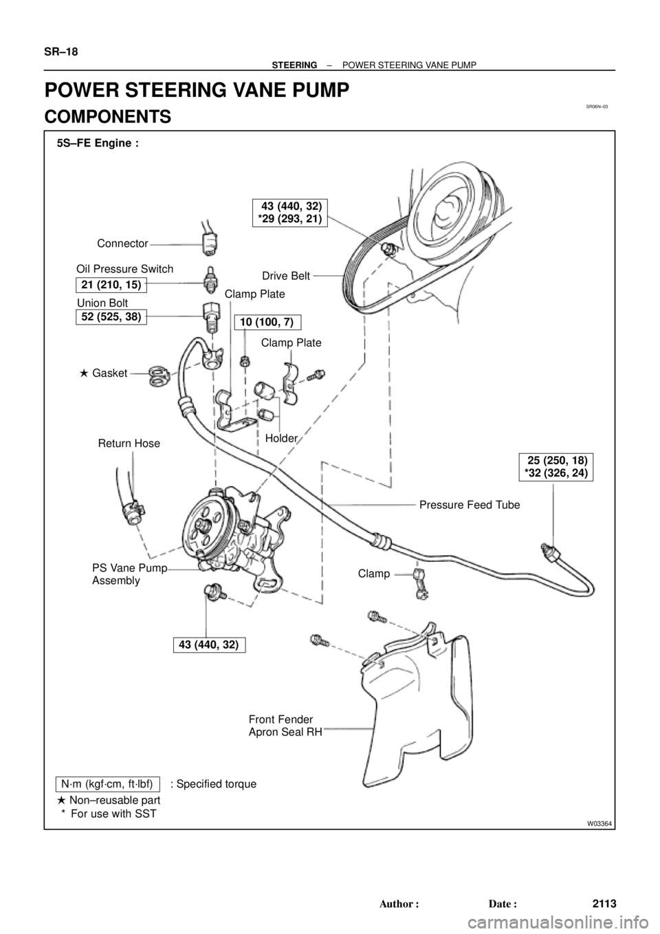
Pressure Feed Tube Connector
Oil Pressure Switch
Drive Belt
Clamp Plate
Clamp Plate
Holder
Clamp
Front Fender
Apron Seal RH PS Vane Pump
AssemblyReturn Hose � Gasket Union Bolt 5S±FE Engine :
21 (210, 15)
43 (440, 32)
*29 (293, 21)
10 (100, 7)
25 (250, 18)
*32 (326, 24)
43 (440, 32)
52 (525, 38)
N´m (kgf´cm, ft´lbf) : Specified torque
� Non±reusable part
For use with SST * SR±18
± STEERINGPOWER STEERING VANE PUMP
2113 Author�: Date�:
POWER STEERING VANE PUMP
COMPONENTS
Page 4309 of 4770
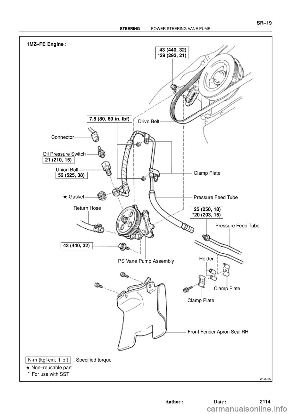
W03365
Drive Belt
Clamp Plate
Pressure Feed Tube
Pressure Feed Tube
Clamp Plate
Clamp Plate
Front Fender Apron Seal RH
N´m (kgf´cm, ft´lbf)
� Non±reusable part
For use with SST: Specified torquePS Vane Pump Assembly Return Hose � Gasket Union Bolt Connector
Oil Pressure Switch
43 (440, 32)
52 (525, 38)
21 (210, 15)
7.8 (80, 69 in.´lbf)
25 (250, 18)
*20 (203, 15)
43 (440, 32)
*29 (293, 21) 1MZ±FE Engine :
Holder
*
± STEERINGPOWER STEERING VANE PUMP
SR±19
2114 Author�: Date�:
Page 4310 of 4770
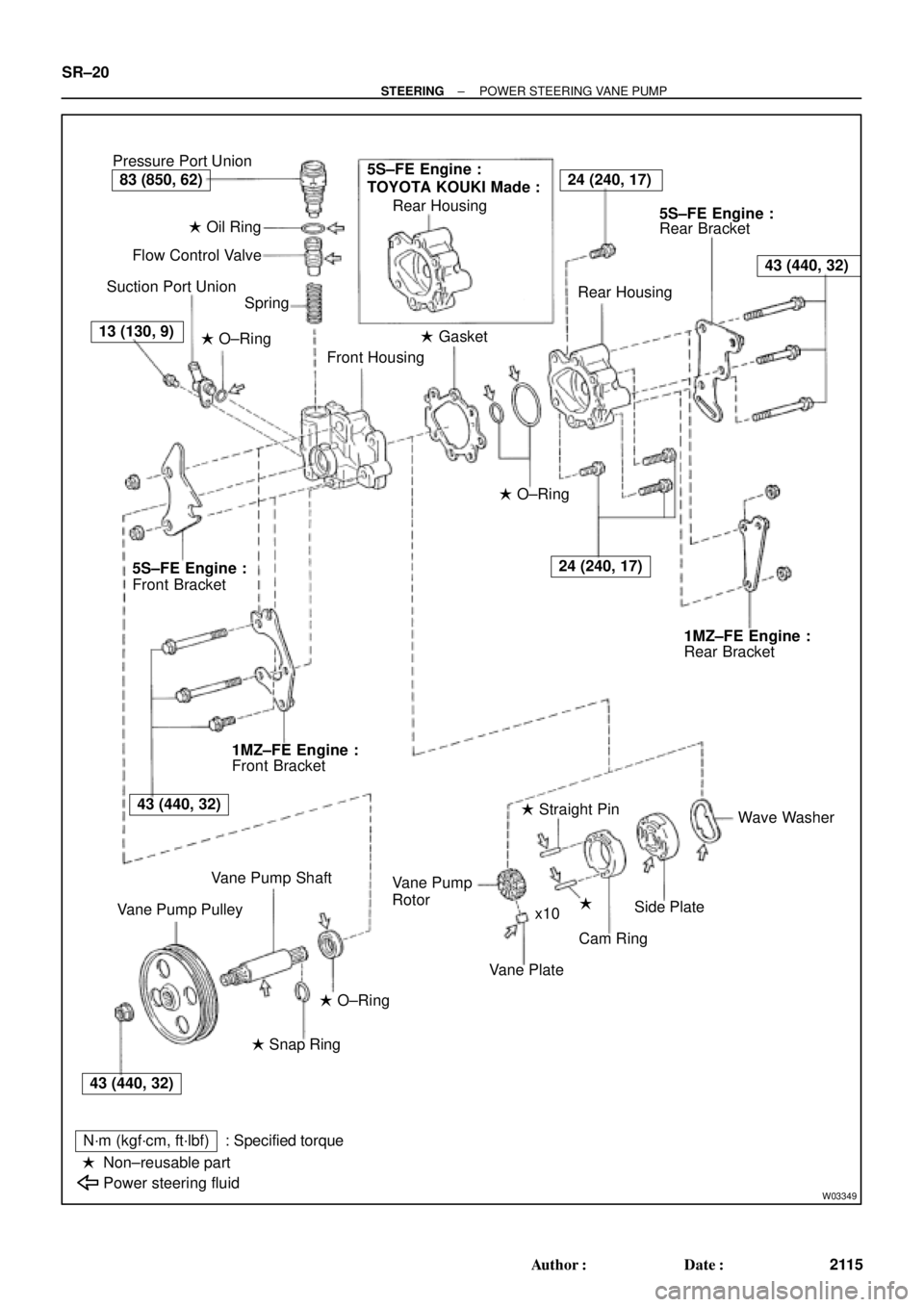
W03349
Pressure Port Union
� Oil Ring
Flow Control Valve
Suction Port Union
Spring
� O±Ring
Front Housing� Gasket Rear Housing
Rear Bracket
Rear Housing
� O±Ring
Rear Bracket
Wave Washer
�
Cam Ring � Straight Pin
Vane Plate Rotor
Side Plate Vane Pump
x10
� O±Ring
� Snap Ring
N´m (kgf´cm, ft´lbf)
Non±reusable part
Power steering fluid: Specified torque Vane Pump Shaft
Vane Pump PulleyFront Bracket Front Bracket
�
5S±FE Engine :
TOYOTA KOUKI Made :24 (240, 17)
43 (440, 32)
24 (240, 17)
83 (850, 62)
13 (130, 9)
5S±FE Engine :5S±FE Engine :
1MZ±FE Engine :1MZ±FE Engine :
43 (440, 32)
43 (440, 32) SR±20
± STEERINGPOWER STEERING VANE PUMP
2115 Author�: Date�:
Page 4312 of 4770

SR06P±01
W03338
Example 5S±FE Engine :
W03339
Example 5S±FE Engine :
SST SR±22
± STEERINGPOWER STEERING VANE PUMP
2117 Author�: Date�:
DISASSEMBLY
NOTICE:
When using a vise, do not overtighten it.
1. MEASURE PS VANE PUMP ROTATING TORQUE
(a) Check that the pump rotates smoothly without abnormal
noise.
(b) Using a torque wrench, check the pump rotating torque.
5S±FE and 1MZ±FE Engines:
Rotating torque:
0.3 N´m (2.8 kgf´cm, 2.4 in.´lbf) or less
2. REMOVE VANE PUMP PULLEY
Using SST, to stop the pulley rotating, remove the nut.
SST 09960±10010 (09962±01000, 09963±01000)
3. REMOVE FRONT AND REAR BRACKETS
Remove the 3 bolts and 2 nuts.
4. REMOVE SUCTION PORT UNION
(a) Remove the bolt.
(b) Remove the O±ring from the union.
5. REMOVE PRESSURE PORT UNION, FLOW CONTROL
VALVE AND SPRING
Remove the O±ring from the union.
6. REMOVE REAR HOUSING
(a) Remove the 4 bolts.
(b) Remove the 2 O±rings from the housing.
7. REMOVE WAVE WASHER
8. REMOVE SIDE PLATE
9. REMOVE GASKET
10. REMOVE CAM RING, 10 VANE PLATES AND VANE
PUMP ROTOR
Using a screwdriver, remove the snap ring from the vane pump
shaft.
NOTICE:
Take care not to drop the plate.
11. REMOVE VANE PUMP SHAFT
12. REMOVE STRAIGHT PINS
Remove the 2 pins from the front housing.
Page 4316 of 4770

SR06R±01
R13458
Inscribed Mark
R01149
Round End
R11292
SR±26
± STEERINGPOWER STEERING VANE PUMP
2121 Author�: Date�:
REASSEMBLY
NOTICE:
When using a vise, do not overtighten it.
1. COAT WITH POWER STEERING FLUID
(See page SR±18)
2. INSTALL VANE PUMP SHAFT
3. INSTALL STRAIGHT PINS
Using a plastic hammer, tap in 2 new pins.
NOTICE:
Be careful not to damage the pins.
4. INSTALL CAM RING
Align the holes of the ring and 2 straight pins, and install the ring
with the inscribed mark facing outward.
5. INSTALL VANE PUMP ROTOR
(a) Install the rotor with the inscribed mark facing outward.
(b) Install a new snap ring to the vane pump shaft.
6. INSTALL VANE PLATES
Install the 10 plates with the round end facing outward.
7. INSTALL GASKET
Install a new gasket.
8. INSTALL SIDE PLATE
Align the holes of the plate and 2 straight pins.
9. INSTALL WAVE WASHER
Install the washer so that its protrusions fit into the slots in the
side plate.
10. INSTALL REAR HOUSING
(a) Coat 2 new O±rings with power steering fluid and install
them to the housing.
(b) Torque the 4 bolts.
5S±FE and 1MZ±FE Engines:
Torque: 24 N´m (240 kgf´cm, 17 ft´lbf)
Page 4317 of 4770
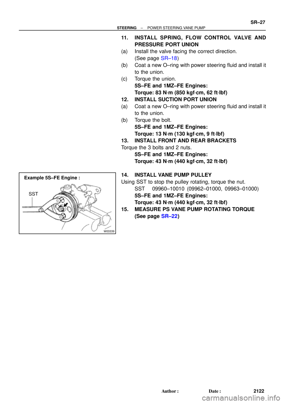
W03339
Example 5S±FE Engine :
SST
± STEERINGPOWER STEERING VANE PUMP
SR±27
2122 Author�: Date�:
11. INSTALL SPRING, FLOW CONTROL VALVE AND
PRESSURE PORT UNION
(a) Install the valve facing the correct direction.
(See page SR±18)
(b) Coat a new O±ring with power steering fluid and install it
to the union.
(c) Torque the union.
5S±FE and 1MZ±FE Engines:
Torque: 83 N´m (850 kgf´cm, 62 ft´lbf)
12. INSTALL SUCTION PORT UNION
(a) Coat a new O±ring with power steering fluid and install it
to the union.
(b) Torque the bolt.
5S±FE and 1MZ±FE Engines:
Torque: 13 N´m (130 kgf´cm, 9 ft´lbf)
13. INSTALL FRONT AND REAR BRACKETS
Torque the 3 bolts and 2 nuts.
5S±FE and 1MZ±FE Engines:
Torque: 43 N´m (440 kgf´cm, 32 ft´lbf)
14. INSTALL VANE PUMP PULLEY
Using SST to stop the pulley rotating, torque the nut.
SST 09960±10010 (09962±01000, 09963±01000)
5S±FE and 1MZ±FE Engines:
Torque: 43 N´m (440 kgf´cm, 32 ft´lbf)
15. MEASURE PS VANE PUMP ROTATING TORQUE
(See page SR±22)
Page 4318 of 4770
SR06S±01
W03361
5S±FE Engine :
1MZ±FE Engine :Pressure Feed Tube
Stopper
Pressure
Feed
StopperTube
W03360
Example 5S±FE Engine :
A
B
W03542
5S±FE Engine :
SST
Fulcrum
Length SR±28
± STEERINGPOWER STEERING VANE PUMP
2123 Author�: Date�:
INSTALLATION
1. INSTALL PRESSURE FEED TUBE
(a) Torque the union bolt with a new gasket.
HINT:
Make sure the stopper of the tube is touching the front bracket,
as shown, then torque the union bolt.
5S±FE and 1MZ±FE Engines:
Torque: 52 N´m (525 kgf´cm, 38 ft´lbf)
(b) Install the oil pressure switch to the union bolt.
5S±FE and 1MZ±FE Engines:
Torque: 21 N´m (210 kgf´cm, 15 ft´lbf)
2. INSTALL PS VANE PUMP ASSEMBLY WITH PRESS-
ER FEED TUBE
Temporarily tighten the 2 (A and B) bolts.
3. INSTALL DRIVE BELT
(a) Adjust drive belt tension.
(See page SR±3)
(b) 5S±FE Engine:
Using SST, torque the A bolt.
SST 09249±63010
Torque: 29 N´m (293 kgf´cm, 21 ft´lbf)
HINT:
Use a torque wrench with a fulcrum length of 300 mm (11.81
in.).