Page 4380 of 4770
SA07T±04
F06530
Suspension Support
Spring Bumper
Link Stabilizer Bar
Shock
Absorber
ABS Speed Sensor
Wire Harness ClampFront Drive Shaft with Coil SpringUpper Seat Bearing
Lower
Insulator
Lower Suspension Arm Lower Suspension
Bushing StopperBrake CaliperInsulator UpperSpring Support No. 2Suspension
Shock Absorber
Coil Spring
Tie Rod End
� Dust
Deflector
� Cotter Pin
� Cotter Pin� Cotter
Pin
Lower Ball jointDisc
Lock Cap ABS Speed Sensor
N´m (kgf´cm, ft´lbf): Specified torque
� Non±reusable part�
80 (820, 59)49 (500, 36)
39 (400, 29)
211 (2,150, 156)
107 (1,090, 79)
29 (300, 22)
123 (1,250, 90)49 (500, 36)
8.0 (82, 71 in.´lbf)
294 (3,000, 217)
206 (2,100, 152)
206 (2,100, 152)
206 (2,100, 152)
127 (1,300, 94)
127 (1,300, 94)
SA±40
± SUSPENSION AND AXLEFRONT LOWER SUSPENSION ARM
1991 Author�: Date�:
FRONT LOWER SUSPENSION ARM
COMPONENTS
Page 4381 of 4770
SA07U±01
W03202
W03203
W03204
± SUSPENSION AND AXLEFRONT LOWER SUSPENSION ARM
SA±41
1992 Author�: Date�:
REMOVAL
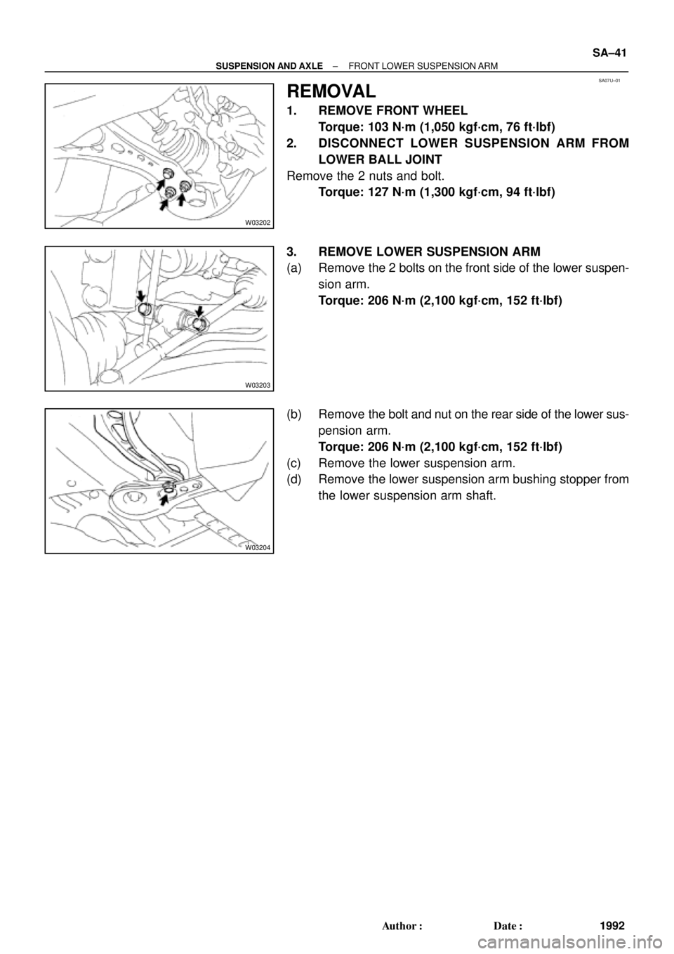
1. REMOVE FRONT WHEEL
Torque: 103 N´m (1,050 kgf´cm, 76 ft´lbf)
2. DISCONNECT LOWER SUSPENSION ARM FROM
LOWER BALL JOINT
Remove the 2 nuts and bolt.
Torque: 127 N´m (1,300 kgf´cm, 94 ft´lbf)
3. REMOVE LOWER SUSPENSION ARM
(a) Remove the 2 bolts on the front side of the lower suspen-
sion arm.
Torque: 206 N´m (2,100 kgf´cm, 152 ft´lbf)
(b) Remove the bolt and nut on the rear side of the lower sus-
pension arm.
Torque: 206 N´m (2,100 kgf´cm, 152 ft´lbf)
(c) Remove the lower suspension arm.
(d) Remove the lower suspension arm bushing stopper from
the lower suspension arm shaft.
Page 4383 of 4770
SA07X±05
F06530
Suspension Support
Spring Bumper
Link Stabilizer Bar
Shock
Absorber
ABS Speed Sensor
Wire Harness ClampFront Drive Shaft with Coil SpringUpper Seat Bearing
Lower
Insulator
Lower Suspension Arm Lower Suspension
Bushing StopperBrake CaliperInsulator UpperSpring Support No. 2Suspension
Shock Absorber
Coil Spring
Tie Rod End
� Dust
Deflector
� Cotter Pin
� Cotter Pin� Cotter
Pin
Lower Ball jointDisc
Lock Cap ABS Speed Sensor
N´m (kgf´cm, ft´lbf): Specified torque
� Non±reusable part�
80 (820, 59)49 (500, 36)
39 (400, 29)
211 (2,150, 156)
107 (1,090, 79)
29 (300, 22)
123 (1,250, 90)49 (500, 36)
8.0 (82, 71 in.´lbf)
294 (3,000, 217)
206 (2,100, 152)
206 (2,100, 152)
206 (2,100, 152)
127 (1,300, 94)
127 (1,300, 94)
± SUSPENSION AND AXLEFRONT LOWER BALL JOINT
SA±43
1994 Author�: Date�:
FRONT LOWER BALL JOINT
COMPONENTS
Page 4385 of 4770
SA07Z±01
N00208
± SUSPENSION AND AXLEFRONT LOWER BALL JOINT
SA±45
1996 Author�: Date�:
INSPECTION
INSPECT BALL JOINT FOR ROTATION CONDITION
(a) As shown in the illustration, flip the ball joint stud back and
forth 5 times, before installing the nut.
(b) Using a torque wrench, turn the nut continuously one turn
each 2 ± 4 seconds and take the torque reading on the 5th
turn.
Turning torque:
1.0 ± 3.4 N´m (10 ± 35 kgf´cm, 8.7 ± 30 in.´lbf)
Page 4386 of 4770
SA080±01
R08850
R08861
SST
SST SA±46
± SUSPENSION AND AXLEFRONT LOWER BALL JOINT
1997 Author�: Date�:
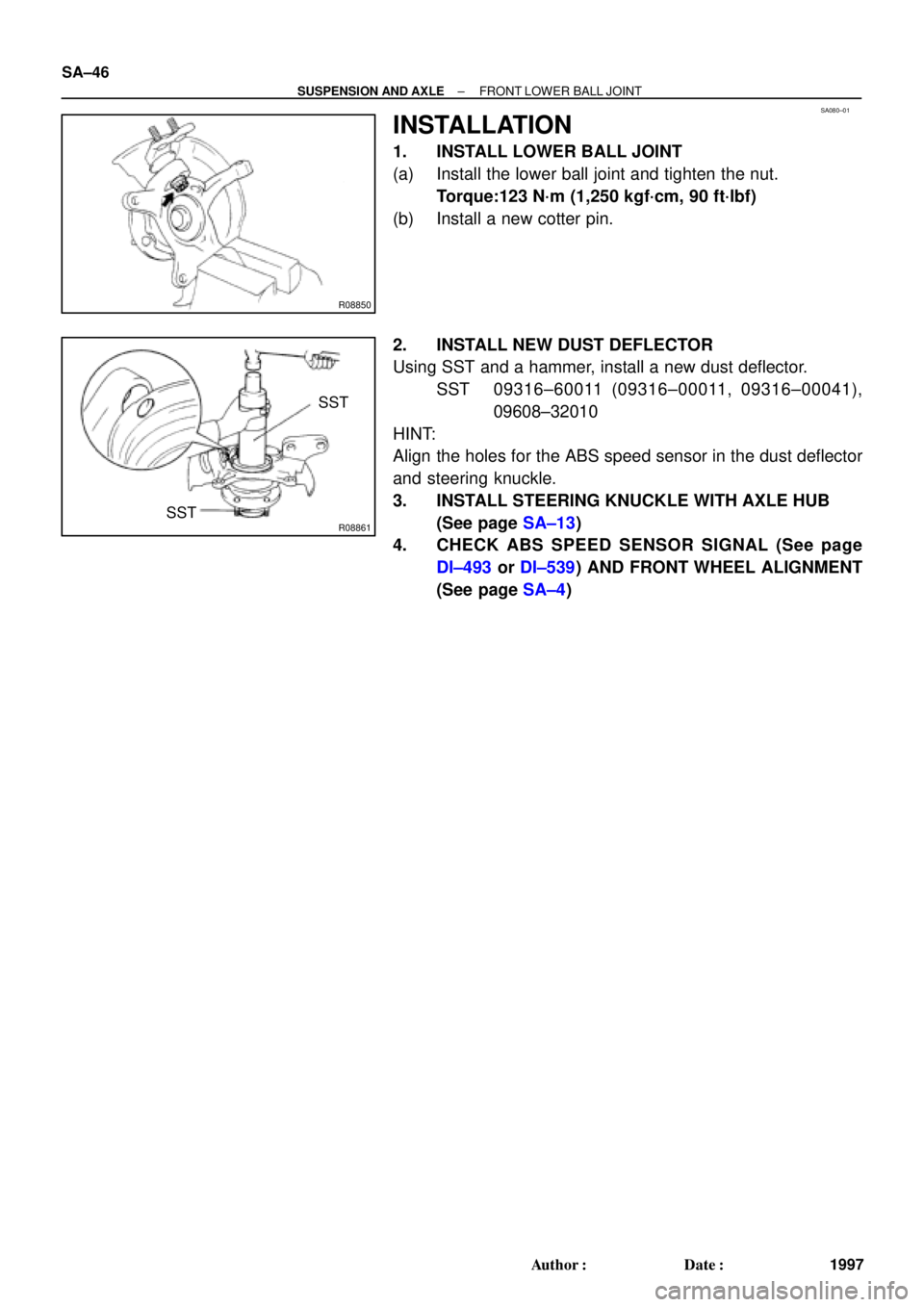
INSTALLATION
1. INSTALL LOWER BALL JOINT
(a) Install the lower ball joint and tighten the nut.
Torque:123 N´m (1,250 kgf´cm, 90 ft´lbf)
(b) Install a new cotter pin.
2. INSTALL NEW DUST DEFLECTOR
Using SST and a hammer, install a new dust deflector.
SST 09316±60011 (09316±00011, 09316±00041),
09608±32010
HINT:
Align the holes for the ABS speed sensor in the dust deflector
and steering knuckle.
3. INSTALL STEERING KNUCKLE WITH AXLE HUB
(See page SA±13)
4. CHECK ABS SPEED SENSOR SIGNAL (See page
DI±493 or DI±539) AND FRONT WHEEL ALIGNMENT
(See page SA±4)
Page 4387 of 4770
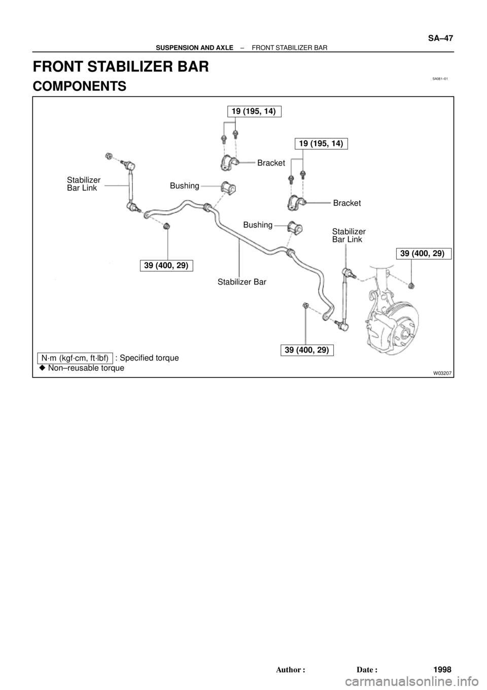
SA081±01
W03207
19 (195, 14)
39 (400, 29)
19 (195, 14)
39 (400, 29)
39 (400, 29)
N´m (kgf´cm, ft´lbf): Specified torque
� Non±reusable torqueStabilizer BarBracket BushingBracket
Stabilizer
Bar Link
Bushing
Stabilizer
Bar Link
± SUSPENSION AND AXLEFRONT STABILIZER BAR
SA±47
1998 Author�: Date�:
FRONT STABILIZER BAR
COMPONENTS
Page 4388 of 4770
SA082±01
W03208
W03209
SA±48
± SUSPENSION AND AXLEFRONT STABILIZER BAR
1999 Author�: Date�:
REMOVAL
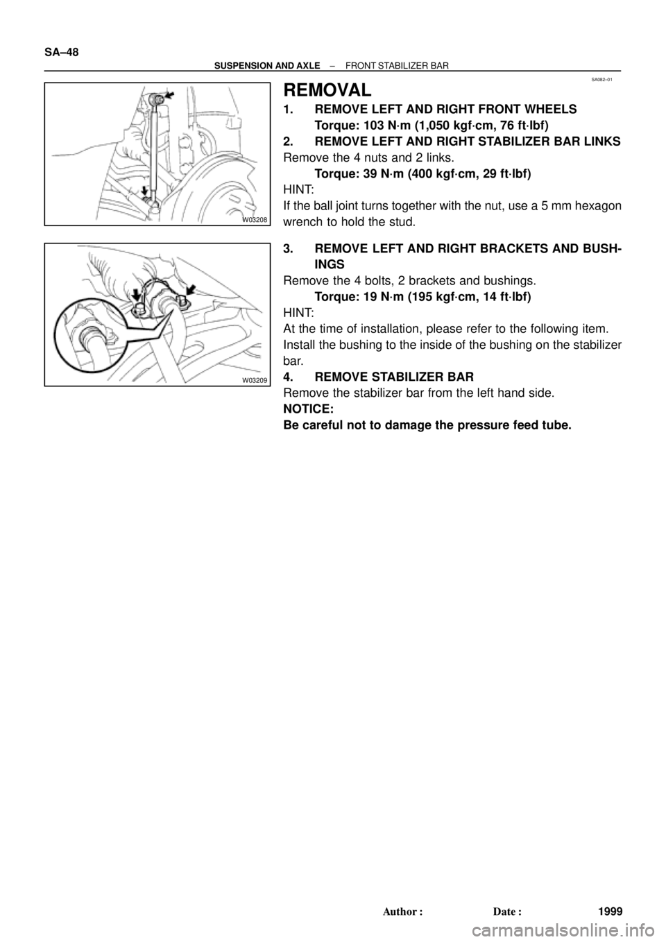
1. REMOVE LEFT AND RIGHT FRONT WHEELS
Torque: 103 N´m (1,050 kgf´cm, 76 ft´lbf)
2. REMOVE LEFT AND RIGHT STABILIZER BAR LINKS
Remove the 4 nuts and 2 links.
Torque: 39 N´m (400 kgf´cm, 29 ft´lbf)
HINT:
If the ball joint turns together with the nut, use a 5 mm hexagon
wrench to hold the stud.
3. REMOVE LEFT AND RIGHT BRACKETS AND BUSH-
INGS
Remove the 4 bolts, 2 brackets and bushings.
Torque: 19 N´m (195 kgf´cm, 14 ft´lbf)
HINT:
At the time of installation, please refer to the following item.
Install the bushing to the inside of the bushing on the stabilizer
bar.
4. REMOVE STABILIZER BAR
Remove the stabilizer bar from the left hand side.
NOTICE:
Be careful not to damage the pressure feed tube.
Page 4389 of 4770
SA083±01
Z00340
± SUSPENSION AND AXLEFRONT STABILIZER BAR
SA±49
2000 Author�: Date�:
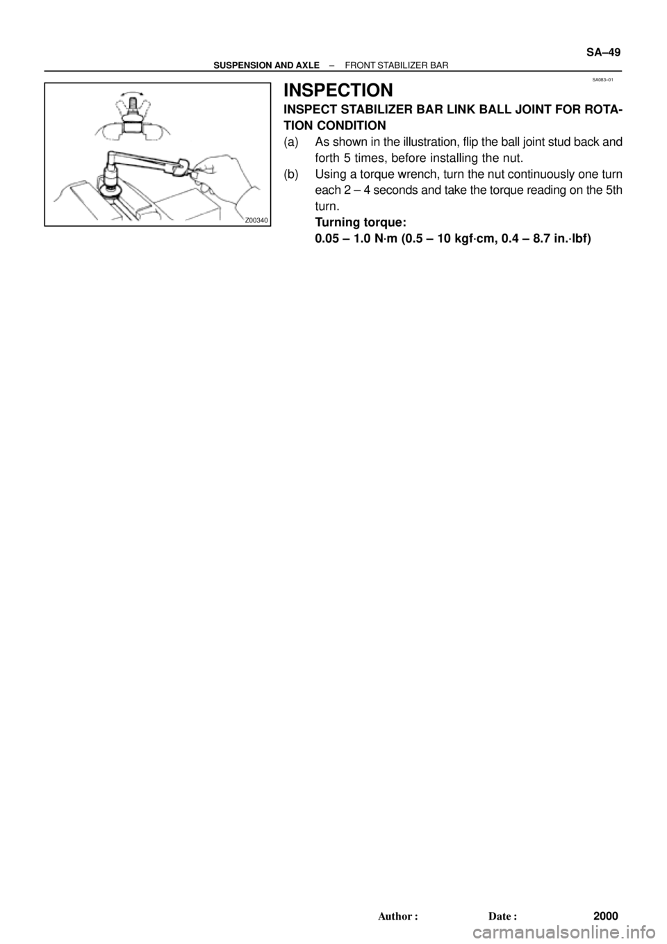
INSPECTION
INSPECT STABILIZER BAR LINK BALL JOINT FOR ROTA-
TION CONDITION
(a) As shown in the illustration, flip the ball joint stud back and
forth 5 times, before installing the nut.
(b) Using a torque wrench, turn the nut continuously one turn
each 2 ± 4 seconds and take the torque reading on the 5th
turn.
Turning torque:
0.05 ± 1.0 N´m (0.5 ± 10 kgf´cm, 0.4 ± 8.7 in.´lbf)