Page 4503 of 4770
SEAT COVER LOOSENESS ± BO020±99 December 17, 1999
Page 3 of 3
6. Reassemble the seat cushion.
7. Bend the locking tabs over the
cushion.
8. After reinstallation of the seat and
manual seat adjuster handle
(if removed), check the seat cushion
retention and seat operation
(sit on seat and push cushion down).
9. Tighten the seat mounting screws to
the torque specifications in the Repair
Manual.Repair
Procedure
(Continued)
Locking Tabs
Page 4522 of 4770
BR002±94
BRAKE VIBRATION AND/OR PULSATIONPage 6 of 6
C. Phase Match Rotor To Hub
± If rotor runout is at the maximum value or greater, (refer to appropriate repair manual)
index the rotor one lug and measure the runout again. Repeat this process, moving the
rotor one lug each time, until the position is found where the runout is at the minimum and
within the maximum value listed in the appropriate repair manual
(See Figure 6 below).
± Tighten lug nuts to the specified torque following a star sequence when installing wheel
(See Figure 7 below).
Note: DO NOT USE AIR IMPACT WRENCH.
Four Holes Five Holes
Figure 7Figure 6
Page 4525 of 4770
BRAKE PAD CLICKING NOISE ± BR004±00 October 20, 2000
Page 2 of 4
There are two types of brake calipers: floating and fixed. Check the type of brake caliper
installed on the vehicle by removing the wheel assembly.
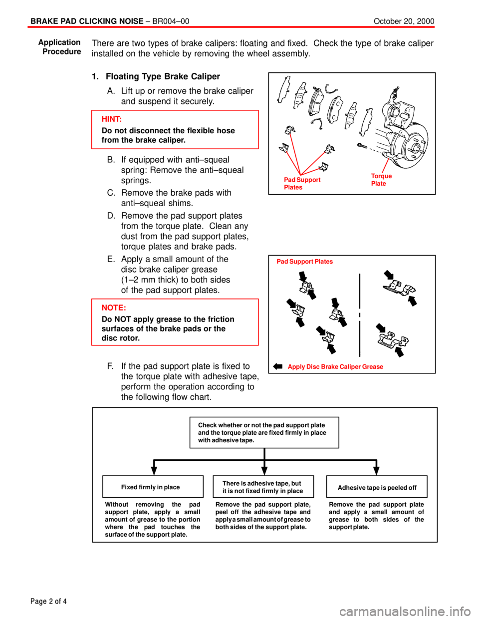
1. Floating Type Brake Caliper
A. Lift up or remove the brake caliper
and suspend it securely.
HINT:
Do not disconnect the flexible hose
from the brake caliper.
B. If equipped with anti±squeal
spring: Remove the anti±squeal
springs.
C. Remove the brake pads with
anti±squeal shims.
D. Remove the pad support plates
from the torque plate. Clean any
dust from the pad support plates,
torque plates and brake pads.
E. Apply a small amount of the
disc brake caliper grease
(1±2 mm thick) to both sides
of the pad support plates.
NOTE:
Do NOT apply grease to the friction
surfaces of the brake pads or the
disc rotor.
F. If the pad support plate is fixed to
the torque plate with adhesive tape,
perform the operation according to
the following flow chart.
Without removing the pad
support plate, apply a small
amount of grease to the portion
where the pad touches the
surface of the support plate.Fixed firmly in placeThere is adhesive tape, but
it is not fixed firmly in placeAdhesive tape is peeled offRemove the pad support plate,
peel off the adhesive tape and
apply a small amount of grease to
both sides of the support plate.Remove the pad support plate
and apply a small amount of
grease to both sides of the
support plate.
Check whether or not the pad support plate
and the torque plate are fixed firmly in place
with adhesive tape.
Application
Procedure
Pad Support
PlatesTorque
Plate
Apply Disc Brake Caliper Grease
Pad Support Plates
Page 4609 of 4770
DOOR MIRROR WIND NOISE ± NV007±00 March 31, 2000
Page 2 of 2
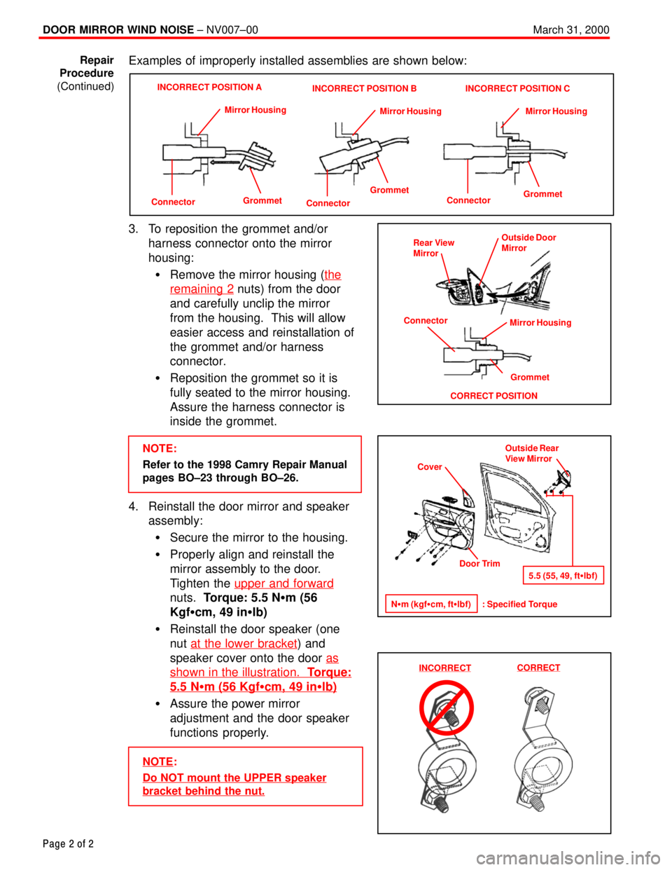
Examples of improperly installed assemblies are shown below:
ConnectorGrommet Mirror Housing
INCORRECT POSITION A
Connector
GrommetMirror Housing
INCORRECT POSITION B
Connector
GrommetMirror Housing
INCORRECT POSITION C
3. To reposition the grommet and/or
harness connector onto the mirror
housing:
�Remove the mirror housing (the
remaining 2 nuts) from the door
and carefully unclip the mirror
from the housing. This will allow
easier access and reinstallation of
the grommet and/or harness
connector.
�Reposition the grommet so it is
fully seated to the mirror housing.
Assure the harness connector is
inside the grommet.
NOTE:
Refer to the 1998 Camry Repair Manual
pages BO±23 through BO±26.
4. Reinstall the door mirror and speaker
assembly:
�Secure the mirror to the housing.
�Properly align and reinstall the
mirror assembly to the door.
Tighten the upper and forward
nuts. Torque: 5.5 N�m (56
Kgf�cm, 49 in�lb)
�Reinstall the door speaker (one
nut at the lower bracket
) and
speaker cover onto the door as
shown in the illustration. Torque:
5.5 N�m (56 Kgf�cm, 49 in�lb)
�Assure the power mirror
adjustment and the door speaker
functions properly.
NOTE:
Do NOT mount the UPPER speaker
bracket behind the nut.
Repair
Procedure
(Continued)
Rear View
Mirror
Grommet
CORRECT POSITIONOutside Door
Mirror
Mirror Housing
Connector
Cover
Door Trim
N�m (kgf�cm, ft�lbf) : Specified TorqueOutside Rear
View Mirror
5.5 (55, 49, ft�lbf)
INCORRECTCORRECT
Page 4635 of 4770
TOYOTA MOTOR SALES U.S.A., INC.
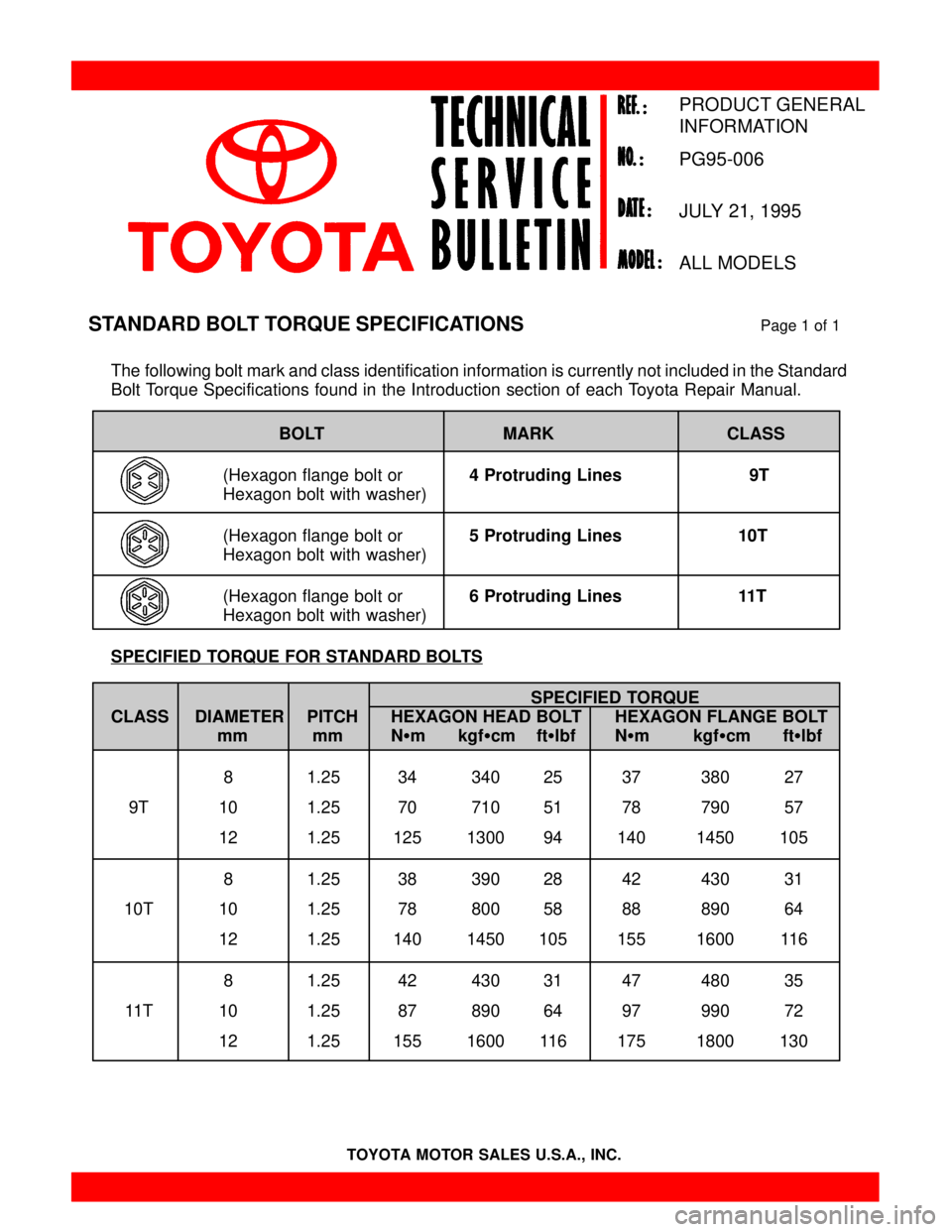
The following bolt mark and class identification information is currently not included in the Standard
Bolt Torque Specifications found in the Introduction section of each Toyota Repair Manual.
BOLT MARK CLASS
(Hexagon flange bolt or 4 Protruding Lines 9T
Hexagon bolt with washer)
(Hexagon flange bolt or 5 Protruding Lines 10T
Hexagon bolt with washer)
(Hexagon flange bolt or 6 Protruding Lines 11T
Hexagon bolt with washer)
SPECIFIED TORQUE FOR STANDARD BOLTS
SPECIFIED TORQUE
CLASS DIAMETER PITCH HEXAGON HEAD BOLT HEXAGON FLANGE BOLT
mm mm N�m kgf�cm ft�lbf N�m kgf�cm ft�lbf
8 1.25 34 340 25 37 380 27
9T 10 1.25 70 710 51 78 790 57
12 1.25 125 1300 94 140 1450 105
8 1.25 38 390 28 42 430 31
10T 10 1.25 78 800 58 88 890 64
12 1.25 140 1450 105 155 1600 116
8 1.25 42 430 31 47 480 35
11T 10 1.25 87 890 64 97 990 72
12 1.25 155 1600 116 175 1800 130
STANDARD BOLT TORQUE SPECIFICATIONSPage 1 of 1
PRODUCT GENERAL
INFORMATION
PG95-006
JULY 21, 1995
ALL MODELS
Page 4654 of 4770
SUSPENSION BALL JOINT INSPECTION ± PG027-02December 4, 2002
Page 2 of 8
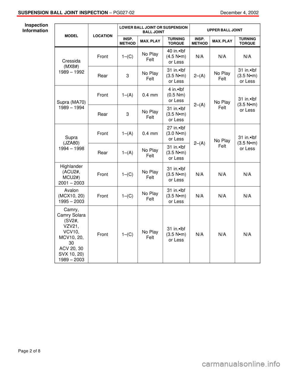
MODELLOCATION
LOWER BALL JOINT OR SUSPENSION
BALL JOINTUPPER BALL JOINT
MODELLOCATION INSP.
METHODMAX. PLAYTURNING
TORQUEINSP.
METHODMAX. PLAYTURNING
TORQUE
Cressida
(MX8#)
Front1±(C)No Play
Felt40 in.�lbf
(4.5 N�m)
or Less
N/AN/AN/A
(MX8#)
1989 ± 1992
Rear3No Play
Felt31 in.�lbf
(3.5 N�m)
or Less
2±(A)No Play
Felt31 in.�lbf
(3.5 N�m)
or Less
Supra (MA70)
Front1±(A)0.4 mm
4 in.�lbf
(0.5 Nm)
or Less
2 (A)No Play31 in.�lbf
(3 5 N�m)Su ra (MA70)
1989 ± 1994
Rear3No Play
Felt31 in.�lbf
(3.5 N�m)
or Less2±(A)No Play
Felt(3.5 N�m)
or Less
Supra
(JZA80)
Front1±(A)0.4 mm
27 in.�lbf
(3.0 N�m)
or Less
2 (A)No Play31 in.�lbf
(3 5 N�m)(JZA80)
1994 ± 1998Rear1±(A)No Play
Felt31 in.�lbf
(3.5 N�m)
or Less2±(A)No Play
Felt(3.5 N�m)
or Less
Highlander
(ACU2#,
MCU2#)
2001 ± 2003
Front1±(C)No Play
Felt31 in.�lbf
(3.5 N�m)
or Less
N/AN/AN/A
Avalon
(MCX10, 20)
1995 ± 2003
Front1±(C)No Play
Felt31 in.�lbf
(3.5 N�m)
or Less
N/AN/AN/A
Camry,
Camry Solara
(SV2#,
VZV21,
VCV10,
MCV10, 20,
30
ACV 20, 30
SVX 10, 20)
1989 ± 2003
Front1±(C)No Play
Felt31 in.�lbf
(3.5 N�m)
or Less
N/AN/AN/A
Inspection
Information
Page 4655 of 4770
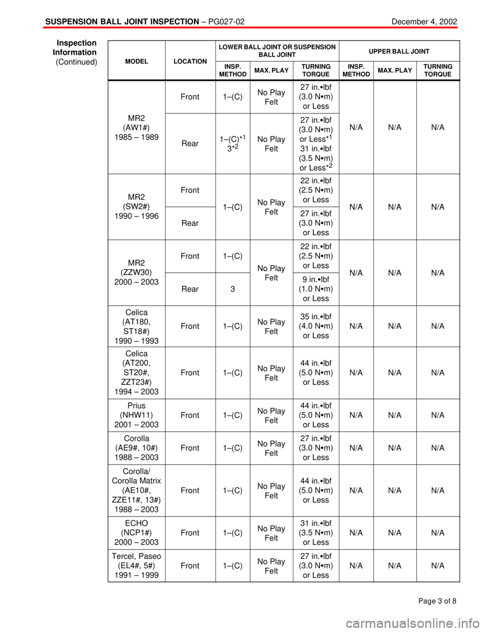
SUSPENSION BALL JOINT INSPECTION ± PG027-02December 4, 2002
Page 3 of 8
MODELLOCATION
LOWER BALL JOINT OR SUSPENSION
BALL JOINTUPPER BALL JOINT
MODELLOCATIONINSP.
METHODMAX. PLAYTURNING
TORQUEINSP.
METHODMAX. PLAYTURNING
TORQUE
Front1±(C)No Play
Felt27 in.�lbf
(3.0 N�m)
or Less
MR2
(AW1#)
1985 ± 1989
Rear1±(C)*1
3*2No Play
Felt
27 in.�lbf
(3.0 N�m)
or Less*
1
31 in.�lbf
(3.5 N�m)
or Less*
2
N/AN/AN/A
MR2
(SW2#)
Front
1 (C)No Play
22 in.�lbf
(2.5 N�m)
or Less
N/AN/AN/A(SW2#)
1990 ± 1996Rear
1±(C)No Play
Felt27 in.�lbf
(3.0 N�m)
or LessN/AN/AN/A
MR2
(ZZW30)
Front1±(C)
No Play
22 in.�lbf
(2.5 N�m)
or Less
N/AN/AN/A(ZZW30)
2000 ± 2003Rear3
No Play
Felt9 in.�lbf
(1.0 N�m)
or LessN/AN/AN/A
Celica
(AT180,
ST18#)
1990 ± 1993
Front1±(C)No Play
Felt35 in.�lbf
(4.0 N�m)
or Less
N/AN/AN/A
Celica
(AT200,
ST20#,
ZZT23#)
1994 ± 2003
Front1±(C)No Play
Felt44 in.�lbf
(5.0 N�m)
or Less
N/AN/AN/A
Prius
(NHW11)
2001 ± 2003
Front1±(C)No Play
Felt44 in.�lbf
(5.0 N�m)
or Less
N/AN/AN/A
Corolla
(AE9#, 10#)
1988 ± 2003
Front1±(C)No Play
Felt27 in.�lbf
(3.0 N�m)
or Less
N/AN/AN/A
Corolla/
Corolla Matrix
(AE10#,
ZZE11#, 13#)
1988 ± 2003
Front1±(C)No Play
Felt44 in.�lbf
(5.0 N�m)
or Less
N/AN/AN/A
ECHO
(NCP1#)
2000 ± 2003
Front1±(C)No Play
Felt31 in.�lbf
(3.5 N�m)
or Less
N/AN/AN/A
Tercel, Paseo
(EL4#, 5#)
1991 ± 1999
Front1±(C)No Play
Felt27 in.�lbf
(3.0 N�m)
or Less
N/AN/AN/A
Inspection
Information
(Continued)
Page 4656 of 4770
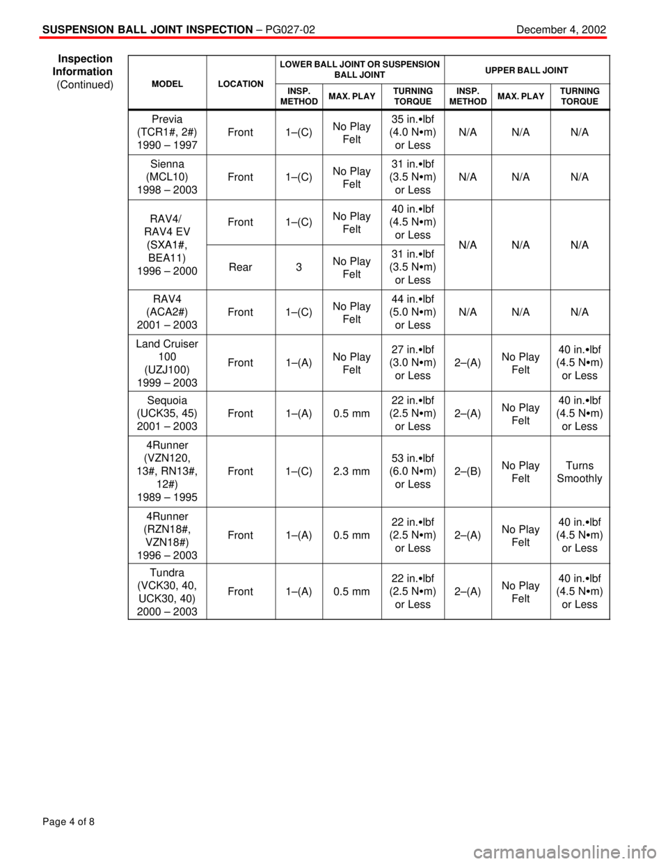
SUSPENSION BALL JOINT INSPECTION ± PG027-02December 4, 2002
Page 4 of 8
MODELLOCATION
LOWER BALL JOINT OR SUSPENSION
BALL JOINTUPPER BALL JOINT
MODELLOCATIONINSP.
METHODMAX. PLAYTURNING
TORQUEINSP.
METHODMAX. PLAYTURNING
TORQUE
Previa
(TCR1#, 2#)
1990 ± 1997
Front1±(C)No Play
Felt35 in.�lbf
(4.0 N�m)
or Less
N/AN/AN/A
Sienna
(MCL10)
1998 ± 2003
Front1±(C)No Play
Felt31 in.�lbf
(3.5 N�m)
or Less
N/AN/AN/A
RAV4/
RAV4 EV
(SXA1#
Front1±(C)No Play
Felt40 in.�lbf
(4.5 N�m)
or Less
N/AN/AN/A(SXA1#,
BEA11)
1996 ± 2000
Rear3No Play
Felt31 in.�lbf
(3.5 N�m)
or LessN/AN/AN/A
RAV4
(ACA2#)
2001 ± 2003
Front1±(C)No Play
Felt44 in.�lbf
(5.0 N�m)
or Less
N/AN/AN/A
Land Cruiser
100
(UZJ100)
1999 ± 2003
Front1±(A)No Play
Felt27 in.�lbf
(3.0 N�m)
or Less
2±(A)No Play
Felt40 in.�lbf
(4.5 N�m)
or Less
Sequoia
(UCK35, 45)
2001 ± 2003
Front1±(A)0.5 mm
22 in.�lbf
(2.5 N�m)
or Less
2±(A)No Play
Felt40 in.�lbf
(4.5 N�m)
or Less
4Runner
(VZN120,
13#, RN13#,
12#)
1989 ± 1995
Front1±(C)2.3 mm
53 in.�lbf
(6.0 N�m)
or Less
2±(B)No Play
FeltTurns
Smoothly
4Runner
(RZN18#,
VZN18#)
1996 ± 2003
Front1±(A)0.5 mm
22 in.�lbf
(2.5 N�m)
or Less
2±(A)No Play
Felt40 in.�lbf
(4.5 N�m)
or Less
Tundra
(VCK30, 40,
UCK30, 40)
2000 ± 2003
Front1±(A)0.5 mm
22 in.�lbf
(2.5 N�m)
or Less
2±(A)No Play
Felt40 in.�lbf
(4.5 N�m)
or Less
Inspection
Information
(Continued)