Page 4407 of 4770
SA08J±01
W03222
W03223
AB
W03224
± SUSPENSION AND AXLEREAR LOWER SUSPENSION ARM AND STRUT ROD
SA±67
2018 Author�: Date�:
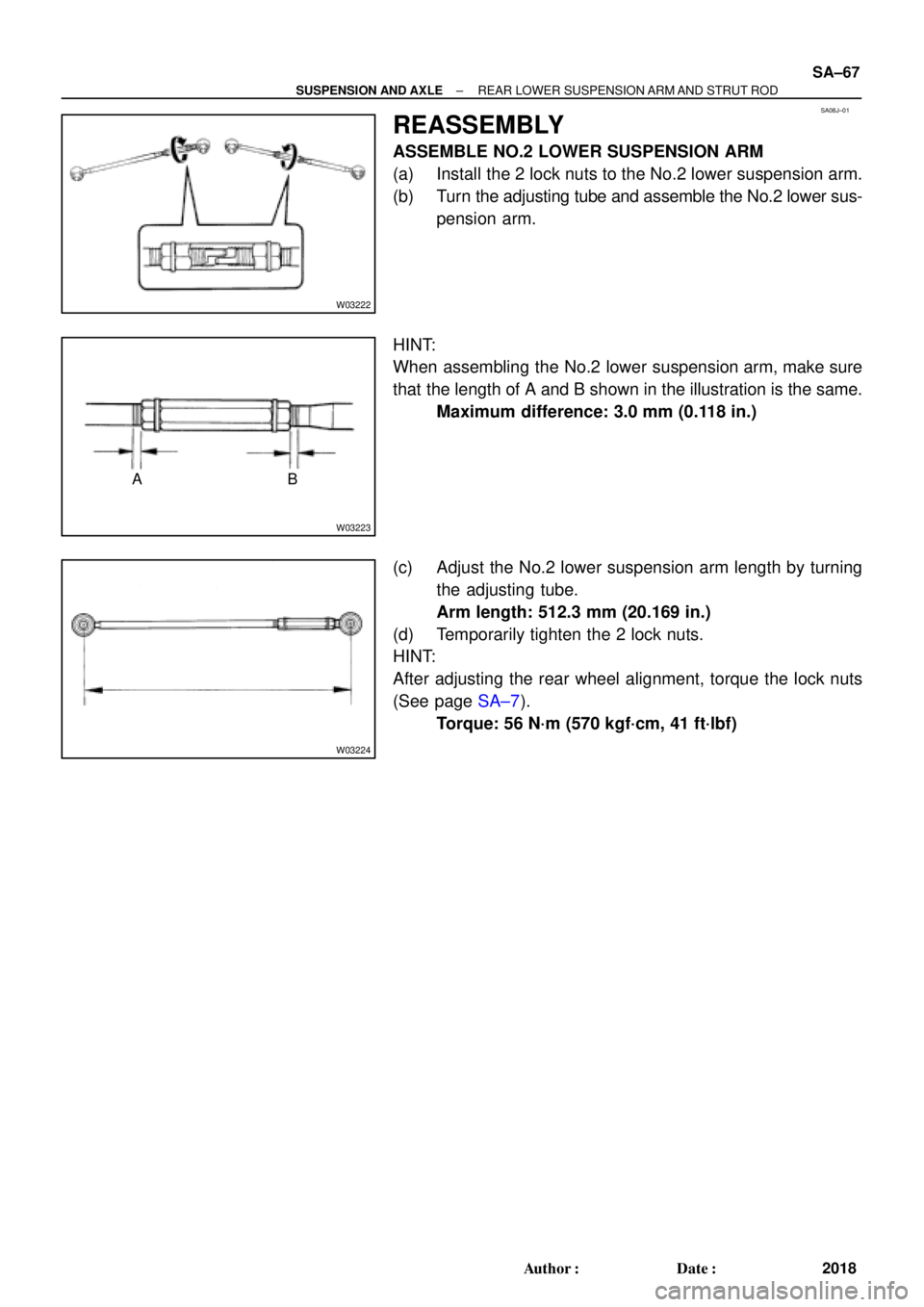
REASSEMBLY
ASSEMBLE NO.2 LOWER SUSPENSION ARM
(a) Install the 2 lock nuts to the No.2 lower suspension arm.
(b) Turn the adjusting tube and assemble the No.2 lower sus-
pension arm.
HINT:
When assembling the No.2 lower suspension arm, make sure
that the length of A and B shown in the illustration is the same.
Maximum difference: 3.0 mm (0.118 in.)
(c) Adjust the No.2 lower suspension arm length by turning
the adjusting tube.
Arm length: 512.3 mm (20.169 in.)
(d) Temporarily tighten the 2 lock nuts.
HINT:
After adjusting the rear wheel alignment, torque the lock nuts
(See page SA±7).
Torque: 56 N´m (570 kgf´cm, 41 ft´lbf)
Page 4409 of 4770
SA08L±01
56 (570, 41)
W03215
Suspension member
Suspension Member Lower Stopper
Suspension Member
Lower Stopper
Sub±Assembly
N´m (kgf´cm, ft´lbf): Specified torque
� Non±reusable torqueStabilizer Bar
Bracket Bushing
Bracket Bushing Stabilizer Bar Link
Exhaust Center PipeClip
Heat Insulator Strut Rod Parking BrakeSuspension Arm Washer
No.2 Lower Suspension Arm
No.1 Lower Suspension Arm
Stabilizer
� Gasket AdjustingNo.2 LOWER SUSPENSION ARM
RH
Tube
Adjusting
Tube
� GasketBar Link Cable Clamp
51 (520, 38)
51 (520, 38)
LH
181 (1,850, 134)
38 (390, 28)56 (570, 41)56 (570, 41)
181 (1,850, 134)
113 (1,150, 83)
5.4 (55, 48 in.´lbf)
39 (400, 29)
113 (1,150, 83)
56 (570, 41)
19 (195, 14)Parking Brake Cable
�
± SUSPENSION AND AXLEREAR STABILIZER BAR
SA±69
2020 Author�: Date�:
REAR STABILIZER BAR
COMPONENTS
Page 4410 of 4770
SA08M±01
W03225
W03226
SA±70
± SUSPENSION AND AXLEREAR STABILIZER BAR
2021 Author�: Date�:
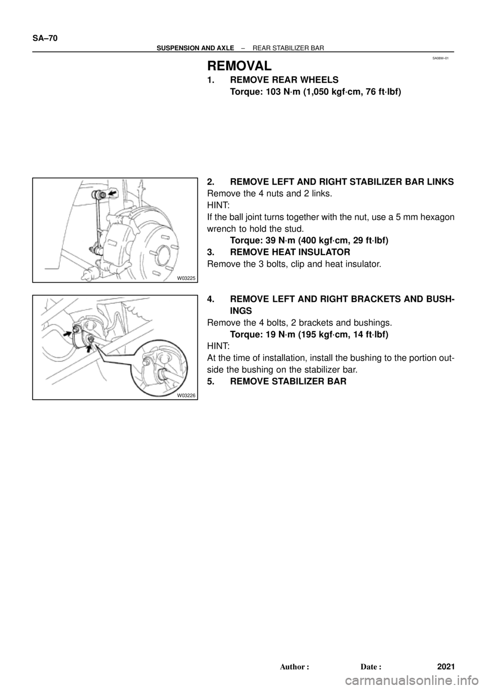
REMOVAL
1. REMOVE REAR WHEELS
Torque: 103 N´m (1,050 kgf´cm, 76 ft´lbf)
2. REMOVE LEFT AND RIGHT STABILIZER BAR LINKS
Remove the 4 nuts and 2 links.
HINT:
If the ball joint turns together with the nut, use a 5 mm hexagon
wrench to hold the stud.
Torque: 39 N´m (400 kgf´cm, 29 ft´lbf)
3. REMOVE HEAT INSULATOR
Remove the 3 bolts, clip and heat insulator.
4. REMOVE LEFT AND RIGHT BRACKETS AND BUSH-
INGS
Remove the 4 bolts, 2 brackets and bushings.
Torque: 19 N´m (195 kgf´cm, 14 ft´lbf)
HINT:
At the time of installation, install the bushing to the portion out-
side the bushing on the stabilizer bar.
5. REMOVE STABILIZER BAR
Page 4411 of 4770
SA08N±01
Z00340
± SUSPENSION AND AXLEREAR STABILIZER BAR
SA±71
2022 Author�: Date�:
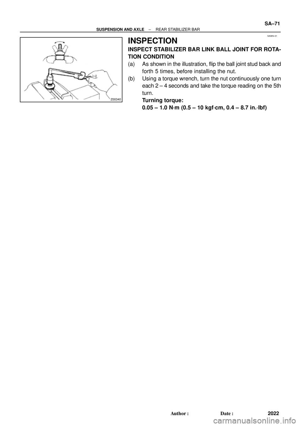
INSPECTION
INSPECT STABILIZER BAR LINK BALL JOINT FOR ROTA-
TION CONDITION
(a) As shown in the illustration, flip the ball joint stud back and
forth 5 times, before installing the nut.
(b) Using a torque wrench, turn the nut continuously one turn
each 2 ± 4 seconds and take the torque reading on the 5th
turn.
Turning torque:
0.05 ± 1.0 N´m (0.5 ± 10 kgf´cm, 0.4 ± 8.7 in.´lbf)
Page 4456 of 4770
1997 CAMRY DOOR MIRROR INSTALLATIONPage 2 of 2
INSTALLATION PROCEDURES (Cont'd):
4. Tighten the three mirror mounting nuts A , B
and C for vehicles without a tweeter.
Torque: 5.5 N.m (56 kgf.cm, 49 in.lbf)
Connect the mirror wire.
5. Tighten the two mirror mounting nuts A and
B for vehicles with a tweeter.
Torque: 5.5 N.m (56 kgf.cm, 49 in.lbf)
Connect the mirror wire.
While lightly pulling the mirror wire
backward, install the tweeter and tighten
nut C.
Torque: 5.5 N.m (56 kgf.cm, 49 in.lbf)
NOTE:Check that the mirror wire is free
from the tweeter bracket.
6. Check the following items:
�There is no clearance between the door
mirror base and the door molding lip.
�The door frame molding lip is not tucked
under the mirror base.
7. Install the front door lower frame bracket
garnish.
8. Install the black cap onto the nut.
BC
A
B
A
C
Molding Lip
Mirror Base
Garnish
Cap
Page 4472 of 4770

Connect the mirror wir")
DOOR MIRROR INSTALLATION ± BO015-00 March 24, 2000
Page 2 of 2
4. For vehicles without a speaker,
tighten the three mirror mounting nuts.
Torque: 5.5 N�m (56 kgf�cm, 49 in�lbf)
Connect the mirror wire.
5. For vehicles with a speaker, tighten
the two mirror mounting nuts.
Torque: 5.5 N�m (56 kgf�cm, 49 in�lbf)
Connect the mirror wire.
While lightly pulling the mirror wire
backward, reinstall the door speaker (one
nut at the lower bracket) onto the door as
shown in the illustration.
Torque: 5.5 N�m (56 kgf�cm, 49 in�lbf)
NOTE:
�Do NOT mount the upper speaker
bracket behind the nut.
6. Check the following items:
�There is no clearance between
the door mirror base and the door
molding lip.
�The mirror wire is free from the
speaker bracket.
�The door frame molding lip is not
tucked under the mirror base.
�The speaker wire does not
contact the mirror mounting
screw.
�Make sure the power mirror
adjustment and the door speaker
functions properly.
7. Install the front door lower frame
bracket garnish/speaker cover.
8. Install the black cap onto the nut.
Installation
Procedure
(Continued)Mounting
Nuts
Mounting
Nuts
Speaker
INCORRECTCORRECT
Mounting Lip
Mirror Base
Speaker Cover
Garnish
Cap
Page 4474 of 4770

POWER SEAT MOTOR CABLE REPAIR TIP ± BO017-01 Revised May 25, 2001
Page 2 of 2
1. Remove the seat assembly from the
vehicle.
Turn the seat over and detach motors
from the mounting brackets.
NOTE:
The lower seat cushion must be
removed from the seat frame to access
the motor mounting screws on some
models.
2. Remove the drive cable from the motor gear boxes. Slide a shrink wrap tube
(3/4º diameter x 1.75º, 3M P/N 36596) on each end of the flex shaft, as shown in
the illustration.
�The Camry and Sienna will require six (6) shrink tubes.
�The Solara will require only one (1) shrink tube.
Camry/Sienna Solara
Front
3. Attach the drive cables to the motors and reinstall motors to the motor mounts.
4. Position each shrink wrap tube so that it overlaps the drive cable housing and motor
housing or gear box housing, as necessary.
5. Using a heat gun, apply heat to the
shrink tubes in a direction from the
center of the drive cable toward the
gear box or motor housing. Be sure to
apply just enough heat to shrink the
tubing.
6. Reinstall the seat cushion to the seat
frame. Tighten the mounting screws to
torque specifications listed in the BO
section of the Repair Manual.
7. Reinstall the seat assembly to the
floor of the vehicle. Assure all
connectors are secure and the power
seat adjustments properly function.
Torque: 37 N�m, 380 kgf�cm, 27 ft�lbs
Repair
Procedure
Heat Gun
Shrink Tube
Page 4479 of 4770

DOOR MIRROR WIND NOISE ± BO019±99 December 3, 1999
Page 2 of 2
INCORRECT POSITION A INCORRECT POSITION B INCORRECT POSITION C
Mirror Housing
ConnectorGrommetMirror Housing
Mirror Housing
Grommet Grommet
ConnectorConnector
3. To reposition the grommet and/or
harness connector onto the mirror
housing:
�Remove the mirror housing (3
nuts) from the door and carefully
unclip the mirror from the housing.
This will allow easier access and
reinstallation of the grommet
and/or harness connector.
�Reposition the grommet so it is
fully seated to the mirror housing.
Assure the harness connector is
inside the grommet.
NOTE:
Refer to the 1998 Camry Repair Manual
pages BO±23 through BO±26.
4. Reinstall the door mirror and speaker
assembly:
�Secure the mirror to the housing.
�Properly align and reinstall the
mirror assembly to the door.
tighten the three nuts. Torque:
5.5 N�m (56 Kgf�cm, 49 in�lb)
�Reinstall the door speaker (one
nut) and speaker cover onto the
door.
�Assure the power mirror
adjustment and the door speaker
functions properly.
ConnectorRear View MirrorOutside Door
Mirror
Mirror Housing
Grommet
CORRECT POSITION
Repair
Procedure
CoverOutside Rear
View Mirror
Door Trim
Specified Torque N�m (kgf�cm, ft�lbf) :5.5 (55, 49, ft�lbf)
:
4. Tighten the three mirror mounting nuts A , B
and C for vehicles without a tweeter.
Torque: 5.5 N.m (56 kgf.cm, 49 in")