Page 4247 of 4770

RS05W±02
H01339
H01352
RS±72
± SUPPLEMENTAL RESTRAINT SYSTEMSIDE AIRBAG SENSOR ASSEMBLY
2217 Author�: Date�:
INSTALLATION
NOTICE:
�Never use SRS parts from another vehicle. When re-
placing parts, replace them with new ones.
�Never reuse the side airbag sensor assembly in-
volved in a collision when the airbag has deployed.
�Never repair a sensor in order to reuse it.
1. INSTALL SIDE AIRBAG SENSOR ASSEMBLY
(a) Using a torx wrench, install the side airbag sensor assem-
bly with the 3 screws.
Torx wrench: T40 (Part No.09042±00020 or locally
manufactured tool)
Torque: 20 N´m (205 kgf´cm, 15 ft´lbf)
(b) Connect the side airbag sensor assembly connector.
NOTICE:
�Connection of the connector is done after the sensor
assembly has been installed. Make sure the sensor
assembly is installed with the specified torque.
�If the sensor assembly has been dropped, or there are
cracks, dents or other defects in the case, bracket or
connector, replace the sensor assembly with a new
one.
�When installing the sensor assembly, take care that
the SRS wiring does not interfere with other parts and
is not pinched between other parts.
�After installation, shake the sensor assembly to
check that there is no looseness.
2. INSTALL FRONT SEAT OUTER BELT RETRACTOR
(See page BO±134)
(a) Install the retractor with the 2 bolts.
Torque:
Upper bolt: 7.5 N´m (76 kgf´cm, 66 in.´lbf)
Lower bolt: 42 N´m (430 kgf´cm, 31 ft´lbf)
(b) Connect the pretensioner connector.
3. INSTALL CENTER PILLAR LOWER GARNISH
4. INSTALL FRONT DOOR SCUFF PLATE
Page 4254 of 4770
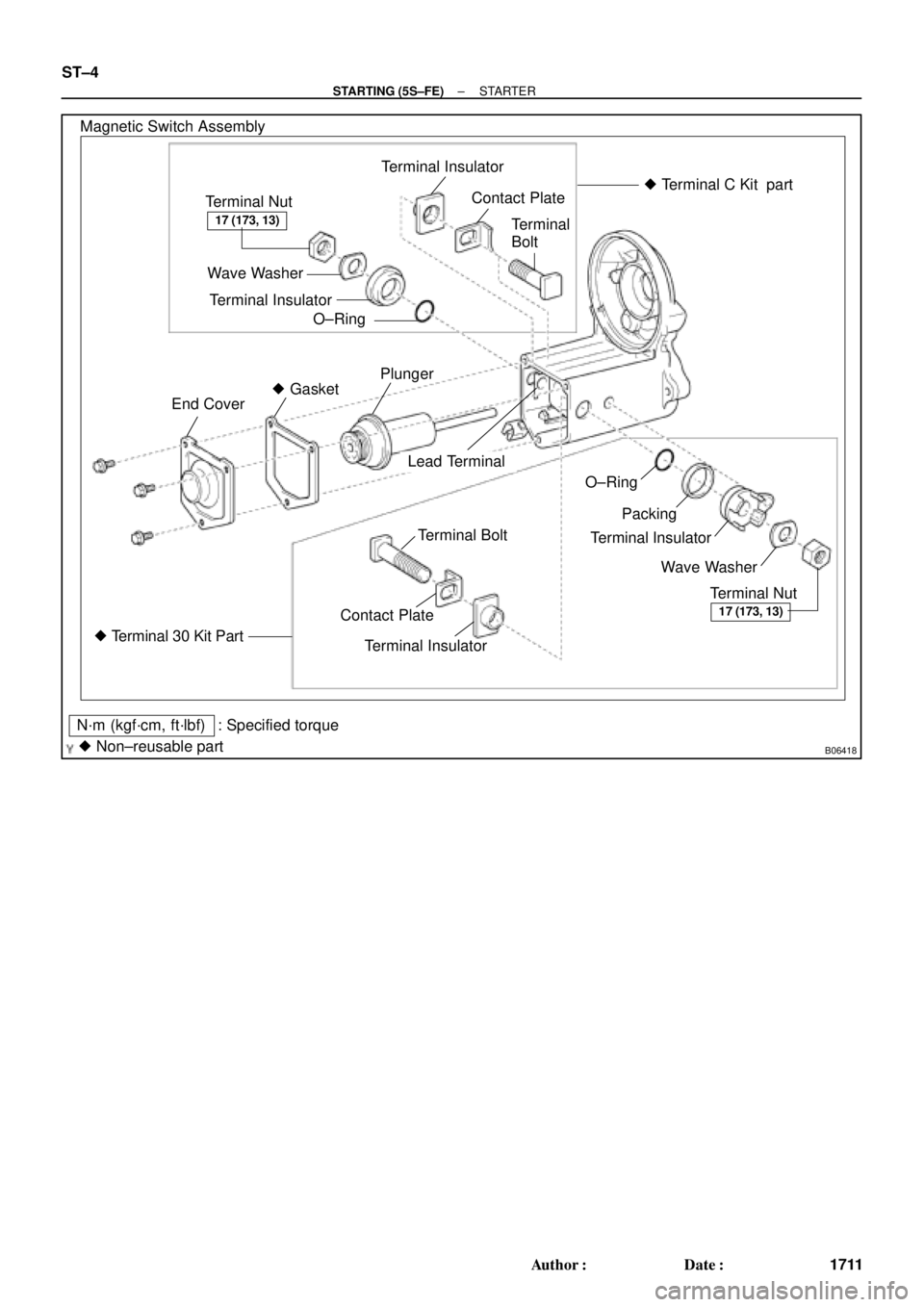
B06418
Magnetic Switch Assembly
Terminal Nut
Wave Washer
Terminal Insulator
O±RingContact Plate
Terminal
Bolt
Terminal Insulator� Terminal C Kit part
Plunger
� Gasket
End Cover
O±Ring
Packing
Terminal Insulator
Wave Washer
Terminal Nut Terminal Bolt
� Terminal 30 Kit PartContact PlateTerminal Insulator
N´m (kgf´cm, ft´lbf)
� Non±reusable part: Specified torque
17 (173, 13)
17 (173, 13)
Lead Terminal
ST±4
± STARTING (5S±FE)STARTER
1711 Author�: Date�:
Page 4255 of 4770
ST03J±01
± STARTING (5S±FE)STARTER
ST±5
1712 Author�: Date�:
REMOVAL
1. REMOVE BATTERY AND TRAY
2. w/ CRUISE CONTROL SYSTEM:
REMOVE CRUISE CONTROL ACTUATOR
(a) Disconnect the actuator connector and clamp.
(b) Remove the 3 bolts, and disconnect the actuator with the bracket.
3. REMOVE STARTER
(a) Disconnect the starter connector.
(b) Remove the 2 bolts, throttle cable clamp (A/T) and starter.
(c) Remove the nut, and disconnect the starter cable.
Torque: 37 N´m (380 kgf´cm, 27 ft´lbf)
Page 4256 of 4770

(4)
(3)
(2)
B01159
ST±6
± STARTING (5S±FE)STARTER
1713 Author�: Date�:
DISASSEMBLY
1. REMOVE DUST PROTECTOR
2. REMOVE FIELD FRAME AND")
ST03K±01
B01156
B01157
Protrusion
Identation
B01158
B01160
(1)
(4)
(3)
(2)
B01159
ST±6
± STARTING (5S±FE)STARTER
1713 Author�: Date�:
DISASSEMBLY
1. REMOVE DUST PROTECTOR
2. REMOVE FIELD FRAME AND ARMATURE
(a) Remove the nut, and disconnect the lead wire from the
magnetic switch terminal.
Torque: 5.9 N´m (60 kgf´cm, 52 in.´lbf)
(b) Remove the 2 through bolts.
Torque: 5.9 N´m (60 kgf´cm, 52 in.´lbf)
(c) Pull out the field frame together with the armature.
HINT:
Align the protrusion of the field frame with the identation of the
magnetic switch.
(d) Remove the O±ring from the field frame.
HINT:
At the time of installation, please refer to following items. Use
a new O±ring.
3. REMOVE STARTER HOUSING, CLUTCH
ASSEMBLY AND GEAR
(a) Remove the 2 screws.
Torque: 5.9 N´m (60 kgf´cm, 52 in.´lbf)
(b) Remove these parts from the magnetic switch:
(1) Starter housing and clutch assembly
(2) Return spring
(3) Idler gear
(4) Bearing
4. REMOVE STEEL BALL
Using a magnetic finger, remove the steel ball from the clutch
shaft hole.
Page 4257 of 4770
B01161
P13528
± STARTING (5S±FE)STARTER
ST±7
1714 Author�: Date�:
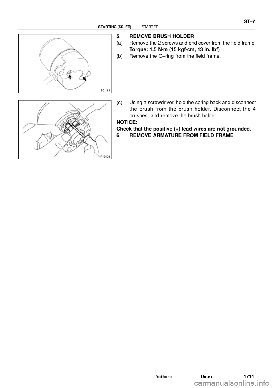
5. REMOVE BRUSH HOLDER
(a) Remove the 2 screws and end cover from the field frame.
Torque: 1.5 N´m (15 kgf´cm, 13 in.´lbf)
(b) Remove the O±ring from the field frame.
(c) Using a screwdriver, hold the spring back and disconnect
the brush from the brush holder. Disconnect the 4
brushes, and remove the brush holder.
NOTICE:
Check that the positive (+) lead wires are not grounded.
6. REMOVE ARMATURE FROM FIELD FRAME
Page 4266 of 4770
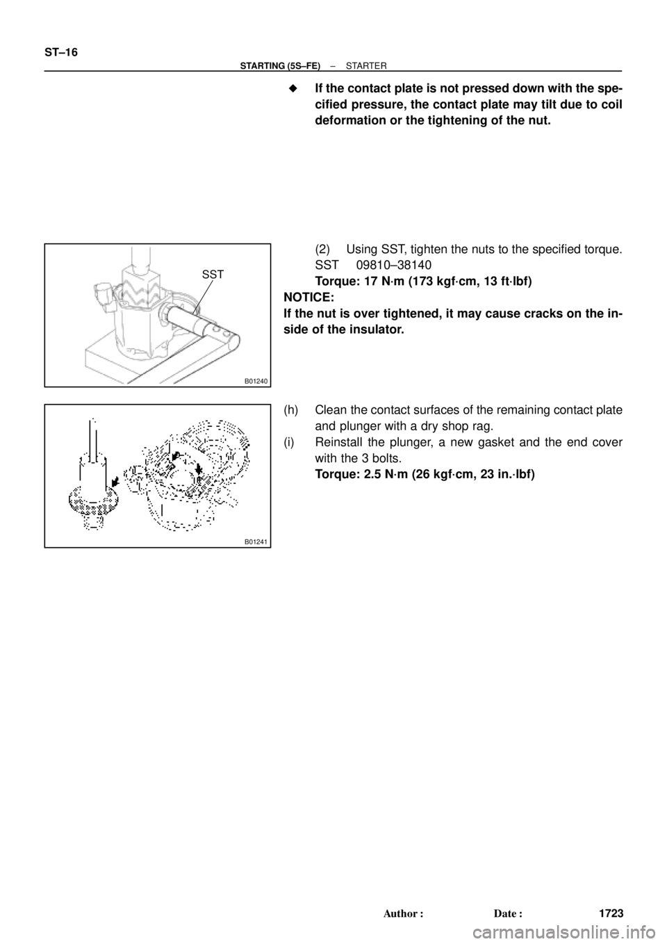
B01240
SST
B01241
ST±16
± STARTING (5S±FE)STARTER
1723 Author�: Date�: �
If the contact plate is not pressed down with the spe-
cified pressure, the contact plate may tilt due to coil
deformation or the tightening of the nut.
(2) Using SST, tighten the nuts to the specified torque.
SST 09810±38140
Torque: 17 N´m (173 kgf´cm, 13 ft´lbf)
NOTICE:
If the nut is over tightened, it may cause cracks on the in-
side of the insulator.
(h) Clean the contact surfaces of the remaining contact plate
and plunger with a dry shop rag.
(i) Reinstall the plunger, a new gasket and the end cover
with the 3 bolts.
Torque: 2.5 N´m (26 kgf´cm, 23 in.´lbf)
Page 4274 of 4770
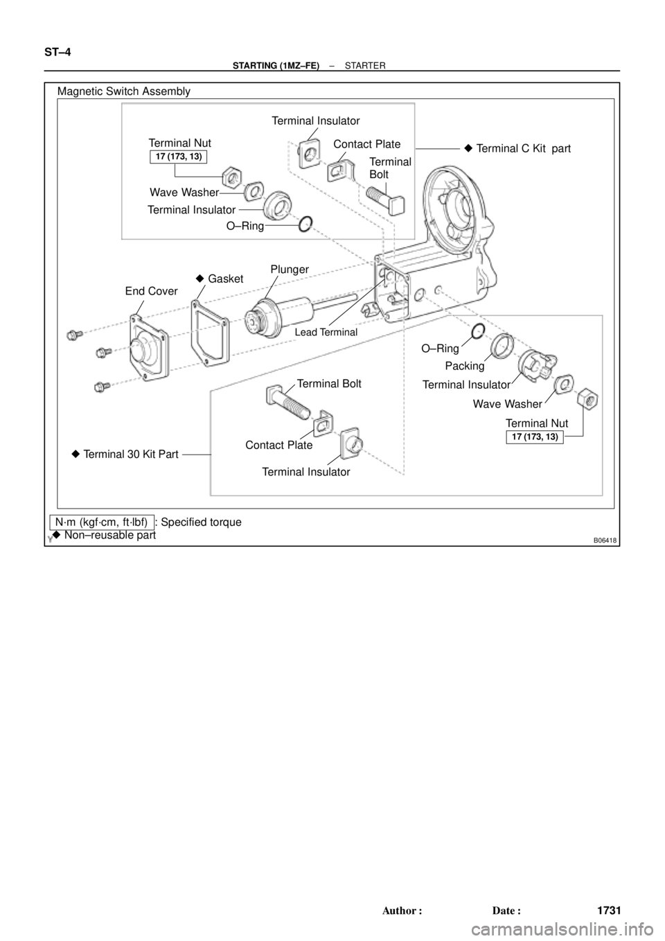
B06418
Magnetic Switch Assembly
Terminal Nut
Wave Washer
Terminal Insulator
O±RingContact Plate
Terminal
Bolt
Terminal Insulator� Terminal C Kit part
Plunger
� Gasket
End Cover
Lead Terminal
O±Ring
Packing
Terminal Insulator
Wave Washer
Terminal Nut Terminal Bolt
� Terminal 30 Kit PartContact PlateTerminal Insulator
N´m (kgf´cm, ft´lbf)
� Non±reusable part: Specified torque
17 (173, 13)
17 (173, 13)
ST±4
± STARTING (1MZ±FE)STARTER
1731 Author�: Date�:
Page 4275 of 4770
ST01V±03
± STARTING (1MZ±FE)STARTER
ST±5
1732 Author�: Date�:
REMOVAL
1. REMOVE BATTERY AND TRAY
2. w/ CRUISE CONTROL SYSTEM:
REMOVE CRUISE CONTROL ACTUATOR
(a) Disconnect the actuator connector and clamp.
(b) Remove the 3 bolts, and disconnect the actuator with the bracket.
3. REMOVE STARTER
(a) Disconnect the starter connector.
(b) Remove the 2 bolts, throttle cable clamp (A/T) and starter.
(c) Remove the nut, and disconnect the starter wire.
Torque: 37 N´m (380 kgf´cm, 27 ft´lbf)