Page 4139 of 4770
SF07V±03
S04506
S06123
(a)
(b)
(d) (e)
(c)
S04527
EGR Gas Temperature
Sensor Bracket
± SFI (1MZ±FE)THROTTLE BODY
SF±39
1538 Author�: Date�:
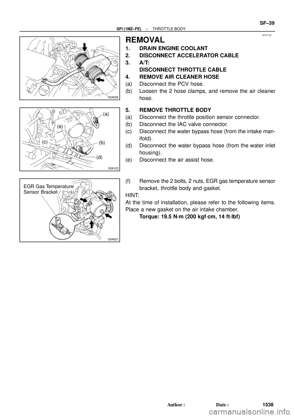
REMOVAL
1. DRAIN ENGINE COOLANT
2. DISCONNECT ACCELERATOR CABLE
3. A/T:
DISCONNECT THROTTLE CABLE
4. REMOVE AIR CLEANER HOSE
(a) Disconnect the PCV hose.
(b) Loosen the 2 hose clamps, and remove the air cleaner
hose.
5. REMOVE THROTTLE BODY
(a) Disconnect the throttle position sensor connector.
(b) Disconnect the IAC valve connector.
(c) Disconnect the water bypass hose (from the intake man-
ifold).
(d) Disconnect the water bypass hose (from the water inlet
housing).
(e) Disconnect the air assist hose.
(f) Remove the 2 bolts, 2 nuts, EGR gas temperature sensor
bracket, throttle body and gasket.
HINT:
At the time of installation, please refer to the following items.
Place a new gasket on the air intake chamber.
Torque: 19.5 N´m (200 kgf´cm, 14 ft´lbf)
Page 4144 of 4770
SF07Z±03
S04742
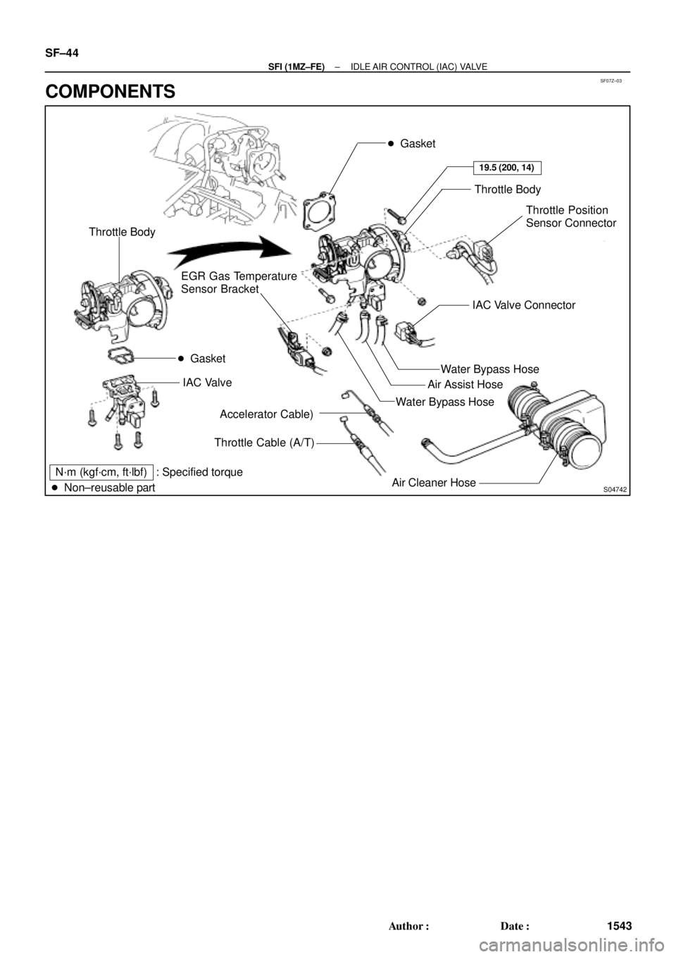
� Gasket
Throttle Body
Throttle Position
Sensor Connector
Water Bypass Hose
Air Cleaner HoseAir Assist Hose
Accelerator Cable)
Throttle Cable (A/T) EGR Gas Temperature
Sensor Bracket
N´m (kgf´cm, ft´lbf) : Specified torque
� Non±reusable partWater Bypass HoseIAC Valve Connector
19.5 (200, 14)
� Gasket Throttle Body
IAC Valve
SF±44
± SFI (1MZ±FE)IDLE AIR CONTROL (IAC) VALVE
1543 Author�: Date�:
COMPONENTS
Page 4149 of 4770
SF084±03
B06467
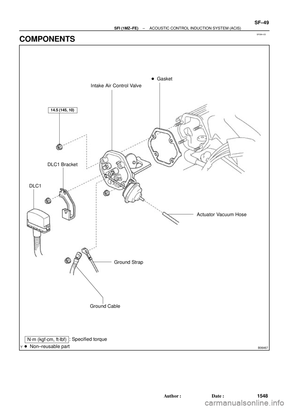
Intake Air Control Valve� Gasket
Actuator Vacuum Hose
Ground Strap
Ground Cable
: Specified torque
� Non±reusable part
14.5 (145, 10)
N´m (kgf´cm, ft´lbf)
DLC1 Bracket
DLC1
± SFI (1MZ±FE)ACOUSTIC CONTROL INDUCTION SYSTEM (ACIS)
SF±49
1548 Author�: Date�:
COMPONENTS
Page 4152 of 4770
SF087±03
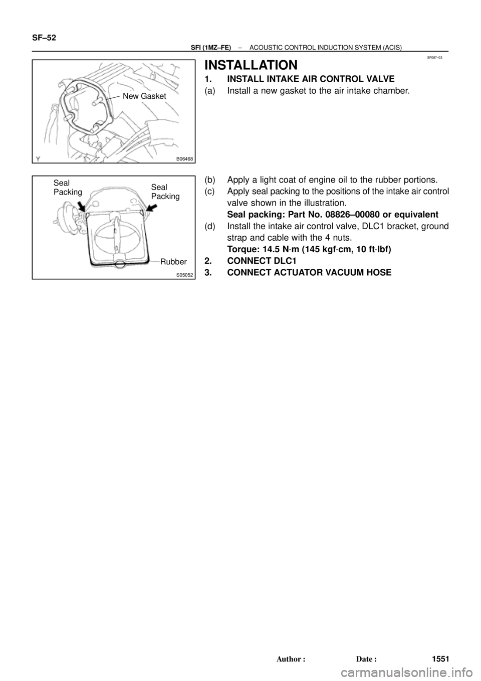
B06468
New Gasket
S05052
Seal
Packing
Rubber Seal
Packing SF±52
± SFI (1MZ±FE)ACOUSTIC CONTROL INDUCTION SYSTEM (ACIS)
1551 Author�: Date�:
INSTALLATION
1. INSTALL INTAKE AIR CONTROL VALVE
(a) Install a new gasket to the air intake chamber.
(b) Apply a light coat of engine oil to the rubber portions.
(c) Apply seal packing to the positions of the intake air control
valve shown in the illustration.
Seal packing: Part No. 08826±00080 or equivalent
(d) Install the intake air control valve, DLC1 bracket, ground
strap and cable with the 4 nuts.
Torque: 14.5 N´m (145 kgf´cm, 10 ft´lbf)
2. CONNECT DLC1
3. CONNECT ACTUATOR VACUUM HOSE
Page 4163 of 4770
SF08I±03
S04759
ECT Switch19 mm
Deep Socket
Wrench
Gasket
S01196S01699Z17274
Ohmmeter
Resistance kW
Temperature °C (°F) Acceptable 30
20
10
5
3
2
1
0.5
0.3
0.2
0.1
40 ±20 0 20 60 80 100
(212) (176) (140) (104) (68) (32) (±4)
± SFI (1MZ±FE)ENGINE COOLANT TEMPERATURE (ECT) SENSOR
SF±63
1562 Author�: Date�:
ENGINE COOLANT
TEMPERATURE (ECT) SENSOR
INSPECTION
1. DRAIN ENGINE COOLANT
2. REMOVE ECT SENSOR
(a) Disconnect the ECT sensor connector.
(b) Using a 19 mm deep socket wrench, remove the ECT
sensor and gasket.
3. INSPECT ECT SENSOR
Using an ohmmeter, measure the resistance between the ter-
minals.
Resistance: Refer to the graph
If the resistance is not as specified, replace the ECT sensor.
4. REINSTALL ECT SENSOR
(a) Install a new gasket to the ECT sensor.
(b) Using a 19 mm deep socket, install the ECT sensor.
Torque: 20 N´m (200 kgf´cm, 14 ft´lbf)
(c) Connect the ECT sensor connector.
5. REFILL WITH ENGINE COOLANT
Page 4166 of 4770

SF08K±03
B06390
VSV Connector for
EVAP
Ground Cable
PCV Hose
Air Intake Chamber
Assembly
ECT Sensor
Connector ECT Sender
Gauge ConnectorEGR Valve Position
Sensor Connector
IAC Valve
Connector
VSV Connector
for EGR
VSV Connector for ACIS
Engine Wire
Engine Coolant
Reservoir HoseAir Assist Hose
Water Bypass Hose No.2 EGR Pipe
Throttle Position
Sensor Connector
No.1 Engine
HangerBrake Booster
Vacuum Hose Air Intake Chamber Stay
Water OutletPS Pressure Tube
�Gasket
19.5 (200, 14)
39 (400, 19)12 (120, 19)
15 (150, 11)
�Gasket
43 (440, 32)
Ground Starp
DLC1
�Gasket
15 (150, 11)
Grand Strap
Connector
�Gasket
39 (400, 29)
V±Bank Cover
Accelerator Cable
Throttle Cable
Air Cleaner
Hose
Purge HoseEGR Gas Temperature
Sensor Connector
Vacuum
HoseWater Bypass Hose
Fuel Inlet Hose
Heater Hose
Intake Manifold Assembly
Injector Connector x 9
Knock Sensor
Connector
Upper Radiator
Hose
Engine
Wire
Band
High±Tension Cord
Set �Gasket
: Specified torque
�Non±reusable partN´m (kgf´cm, ft´lbf)
�Retainer
Knock Sensor
SF±66
± SFI (1MZ±FE)KNOCK SENSOR
1565 Author�: Date�:
KNOCK SENSOR
COMPONENTS
Page 4167 of 4770
SF08L±03
P20115
SSTKnock Sensor 1
Knock Sensor 2
P01630
Ohmmeter
No Continuity
± SFI (1MZ±FE)KNOCK SENSOR
SF±67
1566 Author�: Date�:
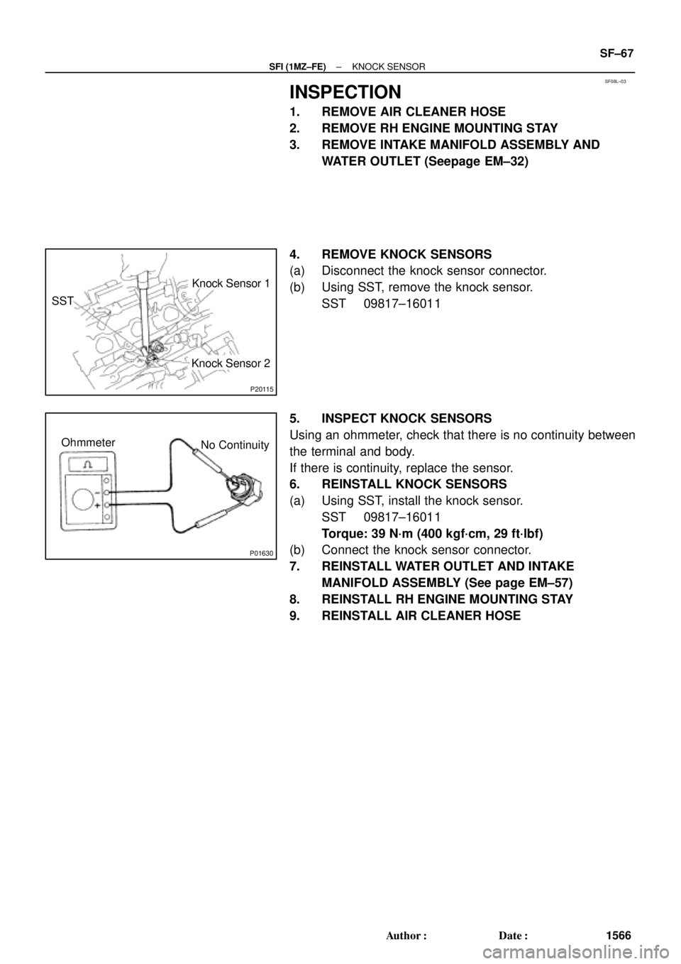
INSPECTION
1. REMOVE AIR CLEANER HOSE
2. REMOVE RH ENGINE MOUNTING STAY
3. REMOVE INTAKE MANIFOLD ASSEMBLY AND
WATER OUTLET (Seepage EM±32)
4. REMOVE KNOCK SENSORS
(a) Disconnect the knock sensor connector.
(b) Using SST, remove the knock sensor.
SST 09817±16011
5. INSPECT KNOCK SENSORS
Using an ohmmeter, check that there is no continuity between
the terminal and body.
If there is continuity, replace the sensor.
6. REINSTALL KNOCK SENSORS
(a) Using SST, install the knock sensor.
SST 09817±16011
Torque: 39 N´m (400 kgf´cm, 29 ft´lbf)
(b) Connect the knock sensor connector.
7. REINSTALL WATER OUTLET AND INTAKE
MANIFOLD ASSEMBLY (See page EM±57)
8. REINSTALL RH ENGINE MOUNTING STAY
9. REINSTALL AIR CLEANER HOSE
Page 4168 of 4770
S05042
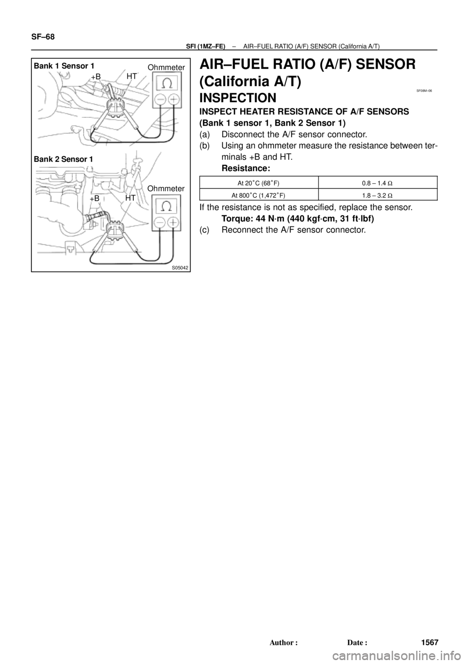
Bank 1 Sensor 1
Bank 2 Sensor 1
Ohmmeter +BHT
+BHTOhmmeter
SF08M±06
SF±68
± SFI (1MZ±FE)AIR±FUEL RATIO (A/F) SENSOR (California A/T)
1567 Author�: Date�:
AIR±FUEL RATIO (A/F) SENSOR
(California A/T)
INSPECTION
INSPECT HEATER RESISTANCE OF A/F SENSORS
(Bank 1 sensor 1, Bank 2 Sensor 1)
(a) Disconnect the A/F sensor connector.
(b) Using an ohmmeter measure the resistance between ter-
minals +B and HT.
Resistance:
At 20°C (68°F)0.8 ± 1.4 W
At 800°C (1,472°F)1.8 ± 3.2 W
If the resistance is not as specified, replace the sensor.
Torque: 44 N´m (440 kgf´cm, 31 ft´lbf)
(c) Reconnect the A/F sensor connector.
 Acceptable 30
20
10
5
3
2
1
0.5
0.3
0.2
0.1
40 ±20 0 20 60 80 100
(212) (176")