Page 4058 of 4770

Z09211
CaliforniaExcept California
S05522
SF±24
± SFI (5S±FE)INJECTOR
1457 Author�: Date�:
(k) If you have no TOYOTA hand±held tester, connect the
positive (+) and negativ")
P01077
ConnectSST
(Wire)
Z09211
CaliforniaExcept California
S05522
SF±24
± SFI (5S±FE)INJECTOR
1457 Author�: Date�:
(k) If you have no TOYOTA hand±held tester, connect the
positive (+) and negative (±) leads from the battery to the
fuel pump connector. (See page SF±6)
(l) Connect SST (wire) to the injector and battery for 15 se-
conds, and measure the injection volume with a gra-
duated cylinder. Test each injector 2 or 3 times.
SST 09842±30070
Volume: 51 ± 63 cm
3 (3.2 ± 3.8 cu in.) per 15 seconds
Difference between each injector:
12 cm
3 (0.7 cu in.) or less
If the injection volume is not as specified, replace the injector.
2. INSPECT LEAKAGE
(a) In the condition above, disconnect the tester probes of
SST (wire) from the battery and check the fuel leakage
from the injector.
SST 09842±30070
Fuel drop: 1 drop or less per 3 minutes
(b) Turn the ignition switch OFF.
(c) Disconnect the negative (±) terminal cable from the bat-
tery.
(d) Remove the SST.
SST 09268±41047, 09842±30070
(e) Disconnect the TOYOTA hand±held tester from the
DLC3.
(f) Reconnect the fuel inlet hose to the fuel filter outlet with
2 new gaskets and the union bolt.
Torque: 29 N´m (300 kgf´cm, 22 ft´lbf)
Page 4060 of 4770

(c) (d) SF±26
± SFI (5S±FE)INJECTOR
1459 Author�: Date�:
(h) Attach the 4 injectors and delivery pipe assembly t")
B06352
S05976
Upward
Turn
Connector
B06351
Gray
Brown No.1
No.2
No.3
No.4
S05289
(b)
(c) (d) SF±26
± SFI (5S±FE)INJECTOR
1459 Author�: Date�:
(h) Attach the 4 injectors and delivery pipe assembly to the
cylinder head.
(i) Temporarily install the 2 bolts holding the delivery pipe to
the cylinder head.
(j) Check that the injectors rotate smoothly.
HINT:
If injectors do not rotate smoothly, the probable cause is incor-
rect installation of O±rings. Replace the O±rings.
(k) Position the injector connector upward.
(l) Tighten the 2 bolts holding the delivery pipe to the cylinder
head.
Torque: 13 N´m (130 kgf´cm, 9 ft´lbf)
(m) Connect the 4 injector connectors.
HINT:
The No.1 and No.3 injector connectors are brown, and the No.2
and No.4 injector connectors are gray.
2. INSTALL CYLINDER HEAD COVER
(a) Install the cylinder head cover. (See page EM±53)
(b) Connect the PCV hose to the intake manifold.
(c) Connect the PCV hose to the cylinder head cover.
(d) Install the engine wire clamp to the mounting bolt of the
No.2 timing belt cover.
(e) Connect the 4 high±tension cords to the spark plugs.
(f) Install the 4 high±tension cords to the clamps on the cylin-
der head cover.
3. CHECK FOR FUEL LEAKS (See page SF±1)
Page 4061 of 4770

Before installing the heated oxygen sensor,
twist the sensor wire counterclockwise
3 and 1/2 turns. HINT:
After installing the heated oxygen sen")
SF0DL±03
B06469
Heated Oxygen Sensor (Bank 1 Sensor 2)
Before installing the heated oxygen sensor,
twist the sensor wire counterclockwise
3 and 1/2 turns. HINT:
After installing the heated oxygen sensor,
check that the sensor wire is not twisted,
if it is twisted, remove the heated oxygen
sensor and reinstall it. �Location of Fuel Tank Cushion
No.1 Fuel Tank
Protector
Fuel Tank Vent
Tube Set Plate
Fuel Pump
Fuel Outlet Tube
Fuel Inlet Pipe Fuel Inlet Pipe Shield
Fuel Tank Cap
Fuel Inlet Pipe Protector
Heated Oxygen Sensor
(Bank 1 Sensor 2)Heat Insulator
Fuel Tank Band
Center Exhaust Pipe � Gasket� Gasket � Gasket
� Non±reusable part
N´m (kgf´cm, ft´lbf): Specified torque
39 (400, 29)
44 (450, 33)
56 (570, 41)
56 (570, 41)
x 8
�
� Gasket
Fuel TankFuel Inlet Hose
Charcoal
Canister
EVAP Line Hose Vent Line Hose
± SFI (5S±FE)FUEL TANK AND LINE
SF±27
1460 Author�: Date�:
FUEL TANK AND LINE
COMPONENTS
CAUTION:
�Always use new gaskets when replacing the fuel tank or component parts.
�Apply the proper torque to all parts tightened
Page 4065 of 4770
SF0DO±03
B00526
Accelerator Cable
Throttle Cable
(A/T)
Throttle Position Sensor
Connector
IAC Valve Connector
Water Bypass Hose
EVAP Hose
IAT Sensor
Connector
VSV Connector
for EVAP Air Cleaner CapPCV Hose Air Cleaner HoseThrottle Body Vacuum Hose
� Gasket
EVAP Hose
EVAP Hose Air Hose
(California)
N´m (kgf´cm, ft´lbf): Specified torque
� Non±reusable part
19 (195, 14)
± SFI (5S±FE)THROTTLE BODY
SF±31
1464 Author�: Date�:
COMPONENTS
Page 4068 of 4770
SF0DR±03
S05534
(a)
(c)
(b)
B01283
SF±34
± SFI (5S±FE)THROTTLE BODY
1467 Author�: Date�:
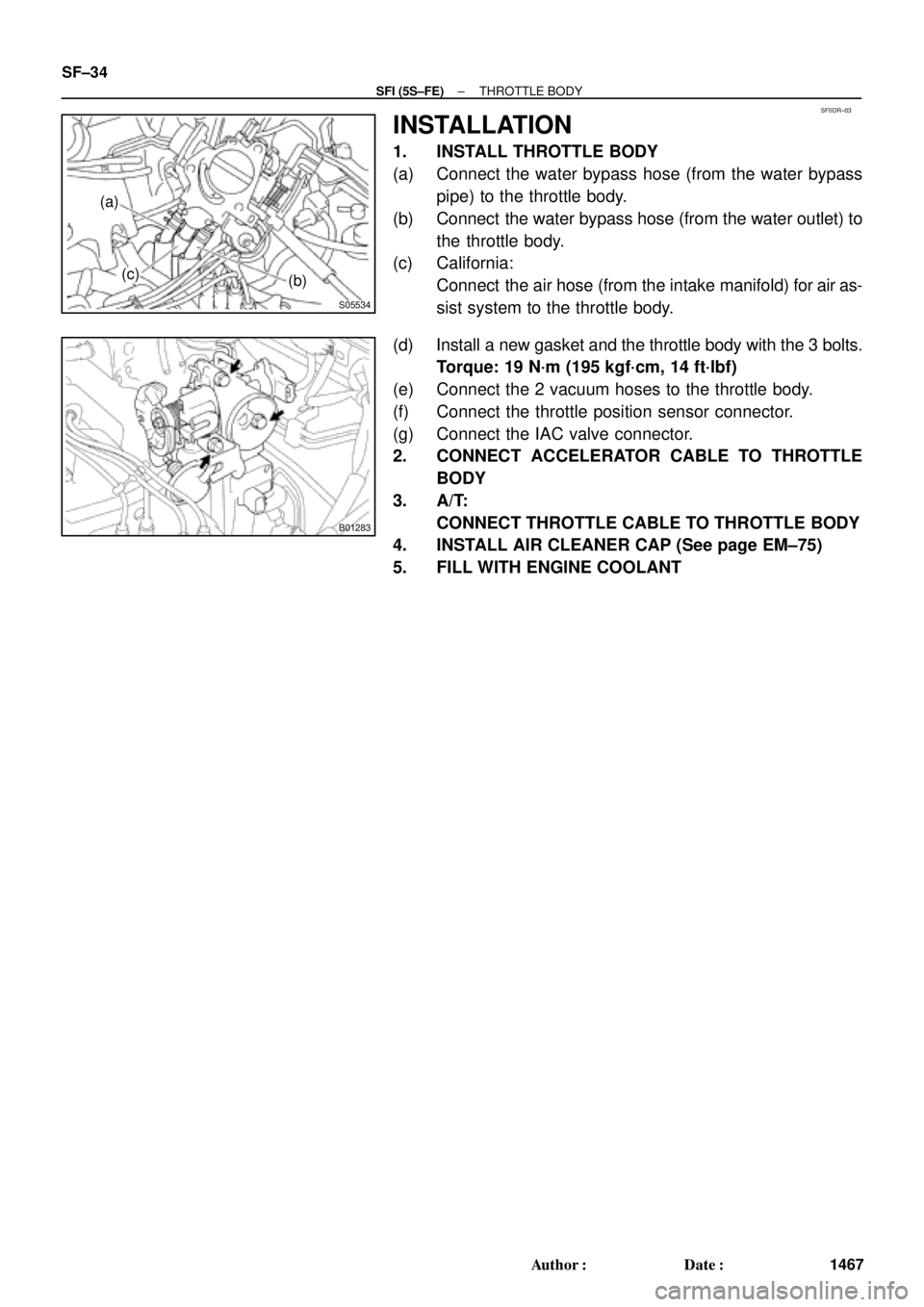
INSTALLATION
1. INSTALL THROTTLE BODY
(a) Connect the water bypass hose (from the water bypass
pipe) to the throttle body.
(b) Connect the water bypass hose (from the water outlet) to
the throttle body.
(c) California:
Connect the air hose (from the intake manifold) for air as-
sist system to the throttle body.
(d) Install a new gasket and the throttle body with the 3 bolts.
Torque: 19 N´m (195 kgf´cm, 14 ft´lbf)
(e) Connect the 2 vacuum hoses to the throttle body.
(f) Connect the throttle position sensor connector.
(g) Connect the IAC valve connector.
2. CONNECT ACCELERATOR CABLE TO THROTTLE
BODY
3. A/T:
CONNECT THROTTLE CABLE TO THROTTLE BODY
4. INSTALL AIR CLEANER CAP (See page EM±75)
5. FILL WITH ENGINE COOLANT
Page 4070 of 4770
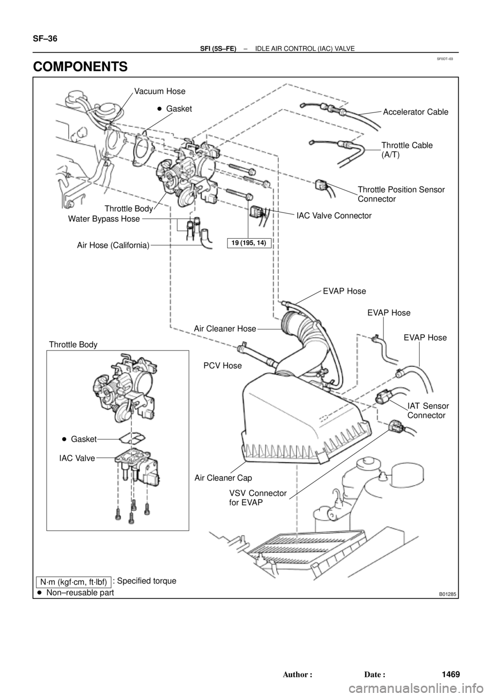
SF0DT±03
B01285
Vacuum Hose
� Gasket
Throttle Body
Water Bypass Hose
Air Hose (California)Accelerator Cable
Throttle Cable
(A/T)
Throttle Position Sensor
Connector
IAC Valve Connector
Air Cleaner Cap Air Cleaner Hose
IAC Valve
VSV Connector
for EVAPEVAP Hose
IAT Sensor
Connector PCV HoseEVAP Hose
EVAP Hose
19 (195, 14)
� Gasket
Throttle Body
N´m (kgf´cm, ft´lbf): Specified torque
� Non±reusable part
SF±36
± SFI (5S±FE)IDLE AIR CONTROL (IAC) VALVE
1469 Author�: Date�:
COMPONENTS
Page 4091 of 4770
SF0EE±03
B06350SST
P01630
Ohmmeter
No Continuity
± SFI (5S±FE)KNOCK SENSOR
SF±57
1490 Author�: Date�:
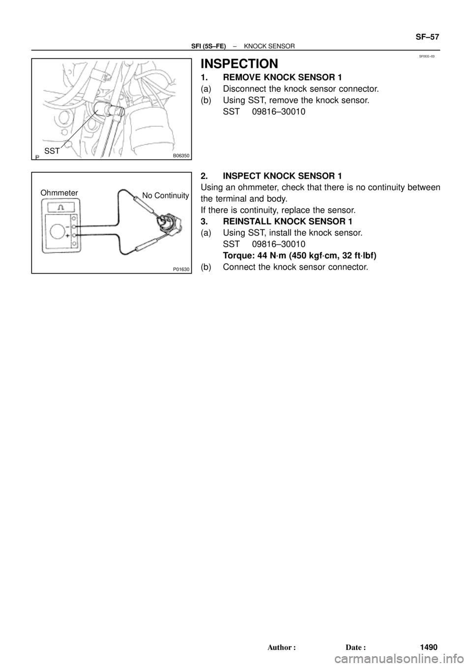
INSPECTION
1. REMOVE KNOCK SENSOR 1
(a) Disconnect the knock sensor connector.
(b) Using SST, remove the knock sensor.
SST 09816±30010
2. INSPECT KNOCK SENSOR 1
Using an ohmmeter, check that there is no continuity between
the terminal and body.
If there is continuity, replace the sensor.
3. REINSTALL KNOCK SENSOR 1
(a) Using SST, install the knock sensor.
SST 09816±30010
Torque: 44 N´m (450 kgf´cm, 32 ft´lbf)
(b) Connect the knock sensor connector.
Page 4092 of 4770
SF0EB±03
B06358
No.3 Exhaust Manifold Heat Insulator
A/F Sensor Connector
Clamp
A/F Sensor
N´m (kgf´cm, ft´lbf): Specified torque
44 (450, 32)
SF±58
± SFI (5S±FE)AIR±FUEL RATIO (A/F) SENSOR (California)
1491 Author�: Date�:
AIR±FUEL RATIO (A/F) SENSOR (California)
COMPONENTS

Throttle Position Sensor
Connector
IAC Valve Connector
Water Bypass Hose
EVAP Hose
IAT Sensor
Connector
VSV Connector
for EVAP Air Cleaner CapPC")
: Specified torque
44 (450, 32)
SF±58
± SFI (5S±FE)AIR±FUEL RATIO (A/F) SENSOR (C")