Page 4026 of 4770

5S±FE Engine :
Drive belt te")
SS06L±03
SS±64
± SERVICE SPECIFICATIONSSTEERING
227 Author�: Date�:
STEERING
SERVICE DATA
ON±VEHICLE INSPECTION
Steering wheel freeplayMaximum30 mm (1.18 in.)
5S±FE Engine :
Drive belt tension New belt95 ± 145 lbf
Drive belt tension Used belt60 ± 100 lbf
1MZ±FE Engine :
Drive belt tension New belt150 ± 185 lbf
Drive belt tension Used belt95 ± 135 lbf
Fluid level rise Maximum5 mm (0.20 in.)
Fluid pressure at idle speed with valve closed Minimum7,845 kPa (80 kgf/cm2, 1,138 psi)
Steering effort at idle speedMaximum5.9 N´m (60 kgf´cm, 52 in.´lbf)
PS VANE PUMP
5S±FE and 1MZ±FE Engines:
Vane pump rotating torqueMaximum0.3 N´m (2.8 kgf´cm, 2.4 in.´lbf)
Oil clearance between pump shaft and bushing STD0.03 ± 0.05 mm (0.0012 ± 0.0020 in.)
Oil clearance between pump shaft and bushingMaximum0.07 mm (0.0028 in.)
Vane plate heightMinimum8.6 mm (0.339 in.)
Vane plate thickness Minimum1.397 mm (0.0550 in.)
Vane plate lengthMinimum14.991 mm (0.5902 in.)
Clearance between the rotor groove and plateMaximum0.035 mm (0.0014 in.)
Vane plate length Pump rotor and cam ring mark
NONE14.999 ± 15.001 mm (0.59051 ± 0.59059 in.)
114.997 ± 14.999 mm (0.59043 ± 0.59051 in.)
214.995 ± 14.997 mm (0.59035 ± 0.59043 in.)
314.993 ± 14.995 mm (0.59027 ± 0.59035 in.)
414.991 ± 14.993 mm (0.59020 ± 0.59027 in.)
Spring free lengthMinimum32.3 mm (1.272 in.)
PS GEAR
Steering rack runout Maximum0.30 mm (0.0118 in.)
Total preload (Control valve rotating torque)0.8 ± 1.4 N´m (8 ± 14 kgf´cm, 6.9 ± 12.2 in.´lbf)
Page 4027 of 4770
7.17263 in.´lbf")
SS06M±01
± SERVICE SPECIFICATIONSSTEERING
SS±65
228 Author�: Date�:
TORQUE SPECIFICATION
Part tightenedN´mkgf´cmft´lbf
STEERING COLUMN
Steering wheel pad set screw (Torx screw)7.17263 in.´lbf
Steering wheel set nut3536026
Intermediate shaft assembly x Control valve shaft3536026
Steering column assembly x Intermediate shaft assembly3536026
Steering column assembly set nut2526019
Turn signal bracket x Column tube77061 in.´lbf
Lower column tube attachment x Column tube1919514
PS VANE PUMP
5S±FE and 1MZ±FE Engines:
Pressure feed tube x Control valve housing 5S±FE Engine32 (25)326 (250)24 (18)
Pressure feed tube x Pressure feed tube 1MZ±FE Engine20 (25)203 (250)15 (18)
Clamp plate set nut 5S±FE Engine101007
Clamp plate set nut 1MZ±FE Engine7.88069 in.´lbf
PS vane pump set bolt A bolt29 (43)293 (440)21 (32)
PS vane pump set bolt B bolt4344032
Oil pressure switch x Union bolt2121015
Union bolt x Pressure feed tube5252538
Vane pump pulley set nut4344032
Front bracket x Rear bracket4344032
Suction port union set bolt131309
Pressure port union8385062
Rear housing set bolt2424017
PS GEAR
Pressure feed tube clamp plate set nut101007
Pressure feed and return tubes x Control valve housing32 (25)326 (250)24 (18)
Stabilizer bar set bolt1919514
PS gear assembly set bolt and nut1811,850134
Turn pressure tube union nut10 (13)102 (130)7 (9)
Tie rod end lock nut7475054
Rack x Rack end60 (83)615 (850)45 (62)
Rack guide spring cap lock nut50 (69)513 (700)37 (51)
Rack housing cap5960043
Selt±locking nut2525018
Control valve housing set bolt1818513
( ): For use without SST
Page 4028 of 4770
SS061±17
SS±66
± SERVICE SPECIFICATIONSSUPPLEMENTAL RESTRAINT SYSTEM
229 Author�: Date�:
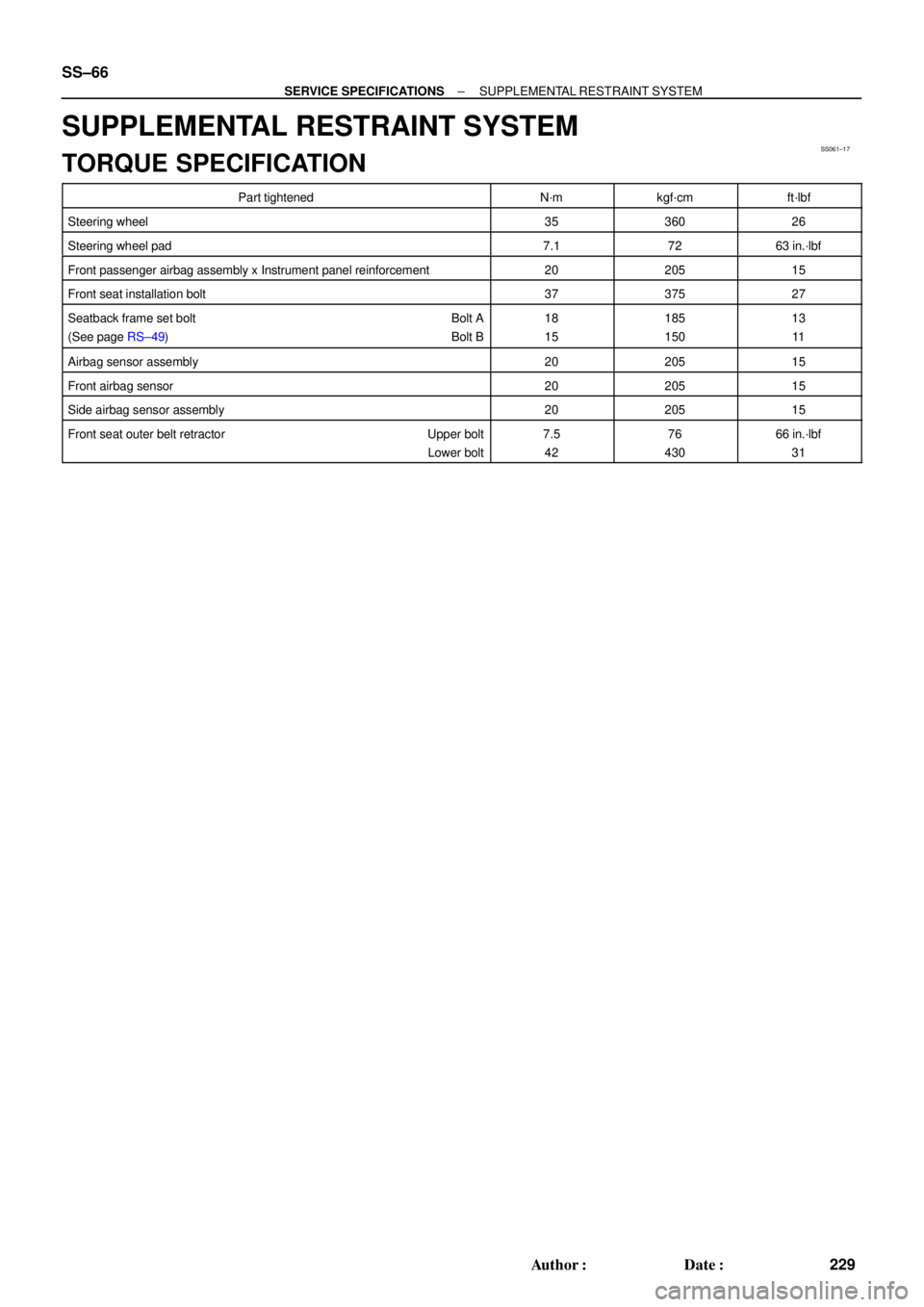
SUPPLEMENTAL RESTRAINT SYSTEM
TORQUE SPECIFICATION
Part tightenedN´mkgf´cmft´lbf
Steering wheel3536026
Steering wheel pad7.17263 in.´lbf
Front passenger airbag assembly x Instrument panel reinforcement2020515
Front seat installation bolt3737527
Seatback frame set bolt Bolt A
(See page RS±49) Bolt B18
15185
15013
11
Airbag sensor assembly2020515
Front airbag sensor2020515
Side airbag sensor assembly2020515
Front seat outer belt retractor Upper bolt
Lower bolt7.5
4276
43066 in.´lbf
31
Page 4031 of 4770

SS0BY±01
± SERVICE SPECIFICATIONSBODY
SS±69
232 Author�: Date�:
BODY
TORQUE SPECIFICATION
Part tightenedN´mkgf´cmft´lbf
FRONT BUMPER±±±
Front bumper cover x Body5.55549 in.´lbf
Front bumper reinforcement x Body3435025
REAR BUMPER±±±
Rear bumper cover x Body5.05043 in.´lbf
Rear bumper reinforcement x Body3435025
HOOD±±±
Hood hinge x Hood2626019
Hood lock x Body8.08071 in.´lbf
FRONT AND REAR DOOR±±±
Front door hinge x Body3131022
Rear door hinge x Body2626019
Door hinge x Door panel2626019
Door lock striker x Body2626019
Outside rear view mirror x Front door panel5.55549
Door inside handle x Door panel3.53531 in.´lbf
Door glass x Window regulator8.08071 in.´lbf
Window regulator x Door panel5.55549 in.´lbf
Door lock x Door panel5.05043 in.´lbf
Door outside handle x Door panel7.07061 in.´lbf
Door check x Body3030022
Door check x Door panel8.08071 in.´lbf
LUGGAGE COMPARTMENT DOOR AND HINGE±±±
Luggage door hinge x Luggage door8.08071 in.´lbf
Luggage door lock striker x Body5.55549 in.´lbf
Luggage door lock x Luggage door5.55549 in.´lbf
FRONT WIPER AND WASHER±±±
Wiper motor assembly x Body2424518
Wiper arm x Wiper pivot5.55549 in.´lbf
SLIDING ROOF±±±
Sliding roof assembly x Body5.55549 in.´lbf
INSTRUMENT PANEL±±±
Front passenger airbag assembly x Reinforcement2020014
Steering wheel lock nut3536026
SEAT±±±
Front Seat (Power Seat for TMC Made)±±±
Hinge cover x Seatback frame1818513
Seatback frame x Power seat adjuster1515011
Seatback frame x Side airbag assembly6.06153 in.´lbf
Front Seat (Manual Seat for TMC Made)±±±
Front seat adjuster x Body3737527
Page 4034 of 4770
SS05W±06
SS±72
± SERVICE SPECIFICATIONSAIR CONDITIONING
235 Author�: Date�:
TORQUE SPECIFICATION
Part tightenedN´mkgf´cmft´lbf
Compressor x Discharge hose101007
Compressor x Suction hose101007
Condenser x Disaharge hose101007
Condenser x Liquid tube1414010
Receiver x Liquid tube5.45548 in.´lbf
Expansion valve x Evaporator5.45548in.´lbf
Compressor x Engine2525018
Compressor x Compressor bracket (1MZ±FE Only)2525018
Drive belt adjusting bar bracket x Compressor2525018
Drive belt adjusting bar bracket x Adjusting bar1818513
Pivot bolt 5S±FE5252038Pivot bolt 5S FE
1MZ±FE5657041
Adjusting lock bolt1818513
Pressure switch x Liquied tube101007
Pressure plate x Compressor13.21359
Suction line (Piping joint)3233024
Suction line (Block joint)101007
Page 4037 of 4770
SFI SYSTEM
SF±3
1436 Author�: Date�:
(b) When connecting the union bolt on t")
S05523
New Gasket
FI1654
SST
30 cm Fulcrum Length
FI0420
Injector
GrommetO±Ring
Delivery PipeCORRECT
WRONG
± SFI (5S±FE)SFI SYSTEM
SF±3
1436 Author�: Date�:
(b) When connecting the union bolt on the high pressure pipe
union, observe these procedures:
(1) Always use 2 new gaskets.
(2) Tighten the union bolt by hand.
(3) Tighten the union bolt to the specified torque.
Torque: 29 N´m (300 kgf´cm, 21 ft´lbf)
(c) When connecting the flare nut on the high pressure pipe
union, observe these procedures:
(1) Apply a light coat of engine oil to the flare nut, and
tighten the flare nut by hand.
(2) Using SST, tighten the flare nut to specified torque.
SST 09631±22020
NOTICE:
Do not rotate the fuel pipe, when tightening the flare nut.
Torque: 28 N´m (285 kgf´cm, 21 ft´lbf) for using SST
HINT:
Use a torque wrench with a fulcrum length of 30 cm (11.81 in.).
(d) Observe these precautions when removing and installing
the injectors.
(1) Never reuse the O±ring.
(2) When placing a new O±ring on the injector, take
care not to damage it in any way.
(3) Coat a new O±ring with spindle oil or gasoline be-
fore installing±never use engine, gear or brake oil.
Page 4041 of 4770
GasketSST (Union Bolt)
SST
(Gauge)
Gasket
S04508
Ohmmeter
4
5
± SFI (5S±FE)FUEL PUMP
SF±7
1440 Author�: Date�:
(d) Install the fuel inlet hose and SST (pres")
S05328
Fuel Inlet
Hose
Gasket
SST (Union)GasketSST (Union Bolt)
SST
(Gauge)
Gasket
S04508
Ohmmeter
4
5
± SFI (5S±FE)FUEL PUMP
SF±7
1440 Author�: Date�:
(d) Install the fuel inlet hose and SST (pressure gauge) to the
fuel filter outlet with the 3 gaskets and SST (union bolt).
SST 09268±45014 (09268±41190, 90405±06167)
Torque: 29 N´m (300 kgf´cm, 21 ft´lbf)
(e) Wipe off any splattered gasoline.
(f) Reconnect the negative (±) terminal cable to the battery.
(g) Connect a TOYOTA hand±held tester to the DLC3.
(See step 1 in check fuel pump operation (a) to (e))
(h) Measure the fuel pressure.
Fuel pressure:
301 ± 347 kPa (3.1 ± 3.5 kgf/cm
2, 44 ± 50 psi)
If pressure is high, replace the fuel pressure regulator.
If pressure is low, check the fuel hoses, fuel hose connections,
fuel pump, fuel filter and fuel pressure regulator.
(i) Disconnect the TOYOTA hand±held tester from the
DLC3.
(j) Start the engine.
(k) Measure the fuel pressure at idle.
Fuel pressure:
301 ± 347 kPa (3.1 ± 3.5 kgf/cm
2, 44 ± 50 psi)
(l) Stop the engine.
(m) Check that the fuel pressure remains as specified for 5
minutes after the engine has stopped.
Fuel pressure:
147 kPa (1.5 kgf/cm
2, 21 psi) or more
If pressure is not as specified, check the fuel pump, pressure
regulator and/or injectors.
(n) After checking fuel pressure, disconnect the negative (±)
terminal cable from the battery and carefully remove the
SST to prevent gasoline from splashing.
SST 09268±45014
(o) Reconnect the fuel inlet hose with 2 new gaskets and the
union bolt.
Torque: 29 N´m (300 kgf´cm, 21 ft´lbf)
(p) Reconnect the negative (±) terminal cable to the battery.
(q) Check for fuel leaks. (See page SF±1)
3. REMOVE REAR SEAT CUSHION
4. REMOVE FLOOR SERVICE HOLE COVER
5. DISCONNECT FUEL PUMP & SENDER GAUGE CON-
NECTOR
6. INSPECT FUEL PUMP RESISTANCE
Using an ohmmeter, measure the resistance between terminals
4 and 5.
Resistance: 0.2 ± 3.0 W at 20°C (68°F)
If the resistance is not as specified, replace the fuel pump.
Page 4043 of 4770
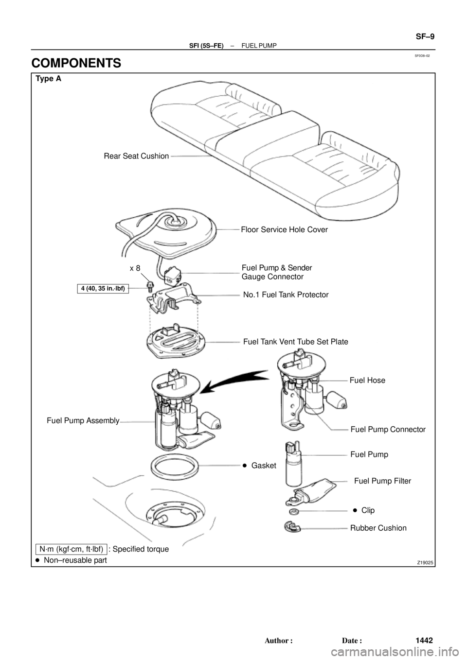
SF0D8±02
Z19025
Type A
Rear Seat Cushion
� Gasket
4 (40, 35 in.´lbf)
Floor Service Hole Cover
Fuel Pump & Sender
Gauge Connector
No.1 Fuel Tank Protector
Fuel Tank Vent Tube Set Plate
Fuel Hose
Fuel Pump Connector
Fuel Pump
Fuel Pump Filter
� Clip
Rubber Cushion Fuel Pump Assembly
N´m (kgf´cm, ft´lbf)
� Non±reusable part: Specified torquex 8
± SFI (5S±FE)FUEL PUMP
SF±9
1442 Author�: Date�:
COMPONENTS