Page 4112 of 4770
FUEL PUMP
1511 Author�: Date�:
REMOVAL
CAUTION:
Do not smoke or work near an open flame when working on
the fuel pump.
1. REMOVE REAR SEAT CUSH")
SF07B±04
S04583
S04592
Vinyl Bag SF±12
± SFI (1MZ±FE)FUEL PUMP
1511 Author�: Date�:
REMOVAL
CAUTION:
Do not smoke or work near an open flame when working on
the fuel pump.
1. REMOVE REAR SEAT CUSHION
2. REMOVE FLOOR SERVICE HOLE COVER
(a) Take out the floor carpet.
(b) Remove the service hole cover.
HINT:
At the time of installation, plaese refer to the following items.
Check for fuel leakage.
3. DISCONNECT FUEL PUMP & SENDER GAUGE
CONNECTOR
4. REMOVE NO.1 FUEL TANK PROTECTOR
Remove the 2 bolts and No.1 fuel tank protector.
Torque: 4 N´m (40 kgf´cm, 35 in.´lbf)
5. DISCONNECT FUEL TUBE (FUEL TUBE CONNEC-
TOR)
CAUTION:
�Perform disconnecting and connecting operations of
the fuel tube connector (quick type) after observing
the precautions. (See page SF±1)
�As there is retained pressure in the fuel pipe line, pre-
vent it from splashing inside the vehicle compart-
ment.
6. REMOVE FUEL PUMP ASSEMBLY FROM FUEL TANK
(a) Remove the 6 bolts and fuel tank vent tube set plate.
Torque: 4 N´m (40 kgf´cm, 35 in.´lbf)
(b) Pull out the fuel pump assembly.
(c) Remove the gasket from the pump assembly.
NOTICE:
�Do not damage the fuel pump filter.
�Be careful that the arm of the sender gauge should
not bent.
HINT:
At the time of installation, plaese refer to the following items.
Install a new gasket to the pump assembly.
Page 4117 of 4770
SF07F±03
B06392
Type A
Rear Seat Cushion
Floor Service Hole Cover
Fuel Pump and Sender
Gauge Connector
No.1 Fuel Tank Protector
Fuel Tank Vent Tube Set Plate
Fuel Pressure
Regulator
Fuel Filter Fuel Pump Assembly
� Gasket
N´m (kgf´cm, ft´lbf)� O±Ring � O±Ring
� Non±reusable part: Specified torque
4 (40,35 in.´lbf)
x 8
± SFI (1MZ±FE)FUEL PRESSURE REGULATOR
SF±17
1516 Author�: Date�:
FUEL PRESSURE REGULATOR
COMPONENTS
Page 4118 of 4770
B06393
Type B
Rear Seat Cushion
Floor Service Hole Cover
Fuel Pump and Sender
Gauge Connector
No.1 Fuel Tank Protector
Fuel Tank Vent Tube Set Plate
Fuel Pressure
Regulator
Fuel Filter Fuel Pump Assembly
� Gasket
N´m (kgf´cm, ft´lbf)� O±Ring � O±Ring
� Non±reusable part: Specified torque
4 (40, 35 in.´lbf)x 8
SF±18
± SFI (1MZ±FE)FUEL PRESSURE REGULATOR
1517 Author�: Date�:
Page 4119 of 4770
SF07G±03
S04591
S04590
± SFI (1MZ±FE)FUEL PRESSURE REGULATOR
SF±19
1518 Author�: Date�:
REMOVAL
1. REMOVE FUEL PUMP ASSEMBLY FROM FUEL TANK
(See page SF±12)
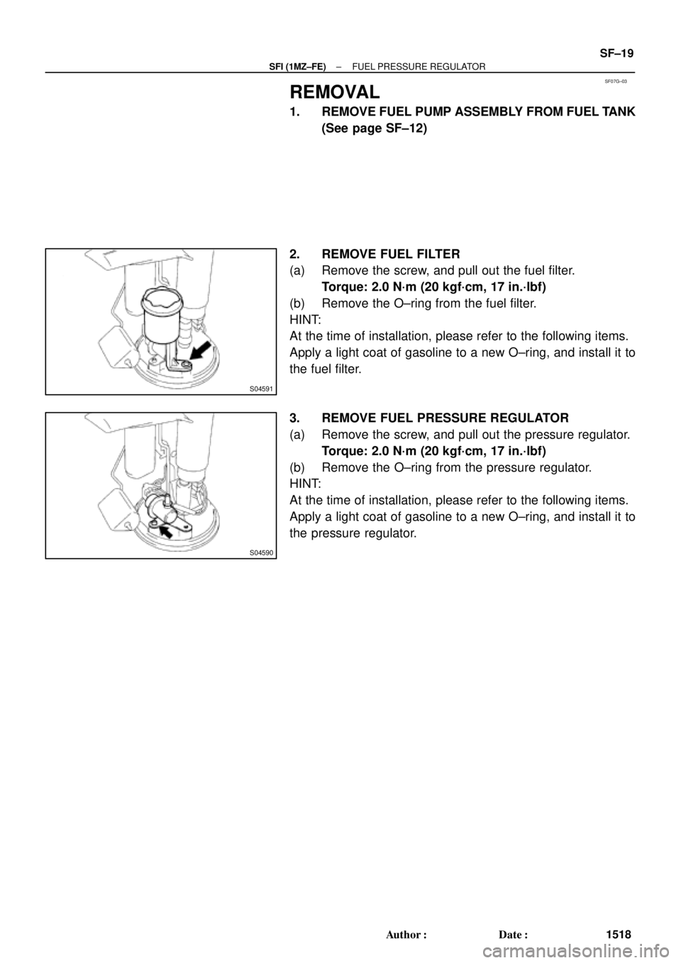
2. REMOVE FUEL FILTER
(a) Remove the screw, and pull out the fuel filter.
Torque: 2.0 N´m (20 kgf´cm, 17 in.´lbf)
(b) Remove the O±ring from the fuel filter.
HINT:
At the time of installation, please refer to the following items.
Apply a light coat of gasoline to a new O±ring, and install it to
the fuel filter.
3. REMOVE FUEL PRESSURE REGULATOR
(a) Remove the screw, and pull out the pressure regulator.
Torque: 2.0 N´m (20 kgf´cm, 17 in.´lbf)
(b) Remove the O±ring from the pressure regulator.
HINT:
At the time of installation, please refer to the following items.
Apply a light coat of gasoline to a new O±ring, and install it to
the pressure regulator.
Page 4122 of 4770
SF07J±03
B06391
Air Intake Chamber Stay
No.1 Engine Hanger
VSV Connector for
EVAP
Ground Cable
Ground Strap
Air Intake Chamber
AssemblyNo.2 EGR
Pipe
VSV Connector
for EGR
Engine Wire
PCV Hose
VSV Connector for ACIS
Spacer
Injector Injector Connector
High±Tension Cord Set PS Pressure Tube
California A/T
Brake Booster
Vacuum Hose
Throttle Position
Sensor Connector
EGR Valve Position
Sensor Connector
IAC Valve
Connector
V±Bank Cover
Accelerator Cable
Throttle Cable
Air Cleaner Hose
EGR Gas Temperature
Sensor Connector Purge Hose
Vacuum
Hose
Water Bypass Hose
Air Assist Hose and Pipe � Gasket
� O±Ring
� O±Ring � Grommet
Injector� Insulator
� Retainer
� Gasket
� Gasket
19.5 (200, 14)
39 (400, 29)
12 (120, 9)
43 (440, 32)
10 (100, 7)19.5 (200, 14)
N´m (kgf´cm, ft´lbf) : Specified torque
� Non±reusable part
DLC1
SF±22
± SFI (1MZ±FE)INJECTOR
1521 Author�: Date�:
COMPONENTS
Page 4129 of 4770
INJECTOR
SF±29
1528 Author�: Date�:
(g) Apply a light coat of spindle oil or gasoline on the place
where a intake manifold touc")
B01021
S04728
Rotate
Outward
B01020
S06525
Align
S05351
± SFI (1MZ±FE)INJECTOR
SF±29
1528 Author�: Date�:
(g) Apply a light coat of spindle oil or gasoline on the place
where a intake manifold touches an O±ring of the injector.
(h) Place the delivery pipes and fuel pipe together with the 6
injectors in position on the intake manifold.
(i) Temporarily install the 4 bolts holding the delivery pipes
to the intake manifold.
(j) Temporarily install the bolt holding the No.1 fuel pipe to
the intake manifold.
(k) Check that the injectors rotate smoothly.
HINT:
If injectors do not rotate smoothly, the probable cause is incor-
rect installation of O±rings. Replace the O±rings.
(l) Position the injector connector outward.
(m) Tighten the 4 bolts holding the delivery pipes to the intake
manifold.
Torque: 10 N´m (100 kgf´cm, 7 ft´lbf)
(n) Tighten the bolt holding the No.1 fuel pipe to the intake
manifold.
Torque: 19.5 N´m (200 kgf´cm, 14 ft´lbf)
2. CONNECT NO.1 FUEL PIPE
(a) Align the alignment marks (white paint) on the No.1 fuel
pipe.
(b) Connect the No.1 fuel pipe (fuel tube connector) to the
fuel filter.
CAUTION:
Perform connecting operations of the fuel tube connector
(quick type) after observing the precaution.
(See page SF±1)
Page 4131 of 4770

Before installing the heated oxygen sensor,
twist the sensor wire counterclockwise
3 and 1/2 turns. HINT:
After installing the heated oxygen sen")
SF07N±03
B06469
Heated Oxygen Sensor (Bank 1 Sensor 2)
Before installing the heated oxygen sensor,
twist the sensor wire counterclockwise
3 and 1/2 turns. HINT:
After installing the heated oxygen sensor,
check that the sensor wire is not twisted,
if it is twisted, remove the heated oxygen
sensor and reinstall it. �
Location of Fuel Tank Cushion
No.1 Fuel Tank
Protector
Fuel Tank Vent
Tube Set Plate
Fuel Pump
Fuel Outlet Tube
Fuel Inlet Pipe Fuel Inlet Pipe ShieldFuel Tank Cap
Fuel Inlet Pipe Protector
Heated Oxygen Sensor
(Bank 1 Sensor 2)Heat Insulator
Fuel Tank Band
Center Exhaust Pipe � Gasket� Gasket � Gasket
� Non±reusable part
N´m (kgf´cm, ft´lbf): Specified torque
39 (400, 29)
44 (450, 33)
56 (570, 41)
56 (570, 41)
x 8
�
� Gasket
Fuel TankFuel Inlet Hose
Charcoal
Canister
EVAP Line Hose
Vent Line Hose
± SFI (1MZ±FE)FUEL TANK AND LINE
SF±31
1530 Author�: Date�:
FUEL TANK AND LINE
COMPONENTS
CAUTION:
�Always use new gaskets when replacing the fuel tank or component parts.
�Apply the proper torque to all parts tightened.
Page 4138 of 4770
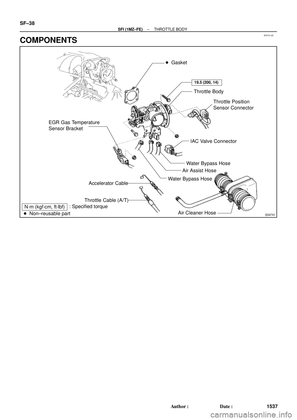
SF07U±03
S04741
EGR Gas Temperature
Sensor Bracket� Gasket
Throttle Body
Throttle Position
Sensor Connector
IAC Valve Connector
Water Bypass Hose
Air Assist Hose
Water Bypass Hose
Air Cleaner Hose Accelerator Cable
Throttle Cable (A/T)
N´m (kgf´cm, ft´lbf)
� Non±reusable part: Specified torque
19.5 (200, 14)
SF±38
± SFI (1MZ±FE)THROTTLE BODY
1537 Author�: Date�:
COMPONENTS