Page 3298 of 4770
Wiring ColorConditionSTD Voltage (V)
CMS e GND WLWB
Ignition switch ON
Main switch OFF10 ± 16 VCMS e GND
(C15")
DI±878
± DIAGNOSTICSCRUISE CONTROL SYSTEM
111 3 Author�: Date�:
Symbols (Terminals No.)Wiring ColorConditionSTD Voltage (V)
CMS e GND WLWB
Ignition switch ON
Main switch OFF10 ± 16 VCMS e GND
(C15±11 e C15±16)W±L e W±BIgnition switch ON
Main switch ONBelow 0.5 V
SPD e GND
(C15 12C15 16)V±W e W±B
Engine start
Car stoppage.Below 1.5 V or
4.7 ± 16 V
(C15±12 e C15±16)VW e WB
During driving (Pulse generated).3 ± 7 V
IDL e GND LRWB
Ignition switch ON
Throttle valve fully opened.10 ± 16 VIDL e GND
(C15±13 e C15±16)L±R e W±BIgnition switch ON
Throttle valve fully closed.Below 1.5 V
OD e GNDYBWB
During cruise control driving
OD switch ON.10 ± 16 VOD e GND
(C15±14 e C15±16)Y±B e W±BDuring cruise control driving
OD switch OFF (3rd driving)Below 1 V
MO e GND RGWB
During cruise control driving
ACC switch hold ON9 ± 15 VMO e GND
(C15±15 e C15±16)R±G e W±BDuring cruise control driving
COAST switch hold ONBelow 1 V
GND e Body Ground
(C15±16 e Body Ground)W±B e Body
GroundConstantBelow 1 V
Page 3302 of 4770
I00004
I00151
ON
2
1
DI±882
± DIAGNOSTICSCRUISE CONTROL SYSTEM
111 7 Author�: Date�:
INSPECTION PROCEDURE
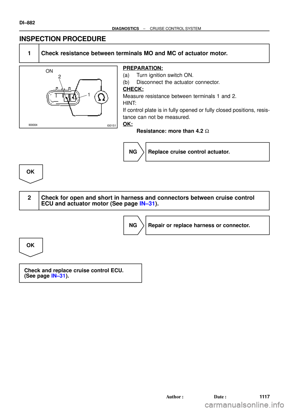
1 Check resistance between terminals MO and MC of actuator motor.
PREPARATION:
(a) Turn ignition switch ON.
(b) Disconnect the actuator connector.
CHECK:
Measure resistance between terminals 1 and 2.
HINT:
If control plate is in fully opened or fully closed positions, resis-
tance can not be measured.
OK:
Resistance: more than 4.2 W
NG Replace cruise control actuator.
OK
2 Check for open and short in harness and connectors between cruise control
ECU and actuator motor (See page IN±31).
NG Repair or replace harness or connector.
OK
Check and replace cruise control ECU.
(See page IN±31).
Page 3304 of 4770
I00157
Instrument panel junction block No.1:
STOP Fuse
I00133
21
43
DI±884
± DIAGNOSTICSCRUISE CONTROL SYSTEM
111 9 Author�: Date�:
INSPECTION PROCEDURE
1 Check STOP fuse.
PREPARATION:
(a) Turn ignition switch OFF.
(b) Remove the STOP fuse from instrument panel junction
block No.1.
CHECK:
Check fuse continuity.
OK:
There is continuity.
NG Replace STOP fuse.
OK
2 Check stop light switch.
PREPARATION:
Disconnect the stop light switch connector.
CHECK:
Check continuity between terminals.
Switch positionContinuity
Switch pin free
(Brake pedal depressed)1 ± 2
Switch pin pushed in
(Brake pedal released)3 ± 4
NG Replace stop light switch.
OK
Page 3305 of 4770
I00311
4
3
± DIAGNOSTICSCRUISE CONTROL SYSTEM
DI±885
1120 Author�: Date�:
3 Check resistance between terminals L and GND of actuator magnetic clutch.
PREPARATION:
(a) Turn ignition switch OFF.
(b) Disconnect the actuator connector.
CHECK:
Measure resistance between terminals 3 and 4.
OK:
Resistance: 34.65 ± 42.35 W.
NG Replace cruise control actuator.
OK
4 Check for open and short in harness and connectors between cruise control
ECU and actuator magnetic clutch, actuator magnetic clutch and body ground
(See page IN±31).
NG Repair or replace harness or connector.
OK
Check and replace cruise control ECU
(See page IN±31).
Page 3306 of 4770
I00055
4
3(+)
(±)
DI±886
± DIAGNOSTICSCRUISE CONTROL SYSTEM
1121 Author�: Date�:
DTC 14 Actuator Mechanical Malfunction
CIRCUIT DESCRIPTION
The circuit detects the rotation position of the actuator control plate and sends a signal to the ECU.
DTC No.Detection ItemTrouble Area
14Cruise control actuator mechanical malfunction.
�Actuator lock: (motor, arm)
�Actuator motor
�Cruise control ECU
WIRING DIAGRAM
See page DI±881.
INSPECTION PROCEDURE
1 Check cruise control actuator arm locking operation
PREPARATION:
(a) Turn ignition switch OFF.
(b) Disconnect the actuator connector.
CHECK:
Connect the positive (+) lead from the battery to the terminal 3
of actuator and the negative (±) lead to terminal 4.
NOTICE:
Do not connect the high tension cables to the wrong bat-
tery terminal. The cruise control actuator will be damaged.
Move the control plate by hand.
OK:
Control plate doesn't move.
NG Replace cruise control actuator.
OK
DI08O±12
Page 3307 of 4770
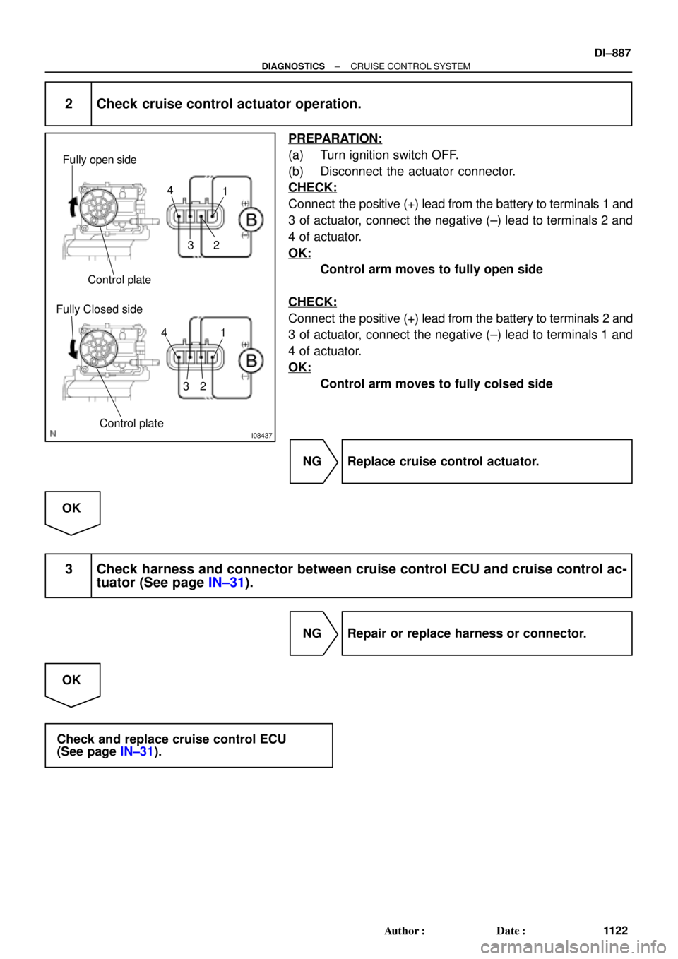
I08437
Fully open side
Fully Closed sideControl plate
Control plate4
321
4
321
± DIAGNOSTICSCRUISE CONTROL SYSTEM
DI±887
1122 Author�: Date�:
2 Check cruise control actuator operation.
PREPARATION:
(a) Turn ignition switch OFF.
(b) Disconnect the actuator connector.
CHECK:
Connect the positive (+) lead from the battery to terminals 1 and
3 of actuator, connect the negative (±) lead to terminals 2 and
4 of actuator.
OK:
Control arm moves to fully open side
CHECK:
Connect the positive (+) lead from the battery to terminals 2 and
3 of actuator, connect the negative (±) lead to terminals 1 and
4 of actuator.
OK:
Control arm moves to fully colsed side
NG Replace cruise control actuator.
OK
3 Check harness and connector between cruise control ECU and cruise control ac-
tuator (See page IN±31).
NG Repair or replace harness or connector.
OK
Check and replace cruise control ECU
(See page IN±31).
Page 3313 of 4770
 (+)
± DIAGNOSTICSCRU")
Input SignalIndicator Light
Blinking Pattern
SET/COAST
switch
RESUME/ACCEL
switch
CANCEL switch2 Pulses
ON
OFF
ON
OFF3 Pulses
ON
OFFSW OFF
SW ON
AB0119
I00168
I00171
ON
CCS
(±) (+)
± DIAGNOSTICSCRUISE CONTROL SYSTEM
DI±893
1128 Author�: Date�:
INSPECTION PROCEDURE
1 Input signal check.
PREPARATION:
See input signal check on page DI±870.
CHECK:
Check the indicator light operation when each of the SET/
COAST, RESUME/ACCEL and CANCEL is turned on.
OK:
SET/COAST, RESUME/ACCEL switch
The signals shown in the table on the left should be
output when each switch is ON. The signal should
disappear when the switch is turned OFF.
CANCEL switch
The indicator light goes off when the cancel switch is
turned ON.
OK Wait and see.
NG
2 Check voltage between terminals CCS of cruise control ECU connector and body
ground.
PREPARATION:
(a) Remove the ECU with connector still connected.
(b) Turn ignition switch ON.
CHECK:
Measure voltage between terminals 18 of ECU connector and
body ground, when each of the SET/COAST, RESUME/AC-
CEL and CANCEL is turned ON.
Switch positionResistance (V)
Neutral10 ± 16 V
RES/ACC0.8 ± 3.7 V
SET/COAST2.5 ± 6.3 V
CANCEL4.2 ± 8.8 V
NG Proceed to next circuit inspection shown on
problem symptoms table (See page DI±879).
OK
Page 3316 of 4770
AB0119
I00167
I00172
ON
IDL
(±) (+)
DI±896
± DIAGNOSTICSCRUISE CONTROL SYSTEM
1131 Author�: Date�:
INSPECTION PROCEDURE
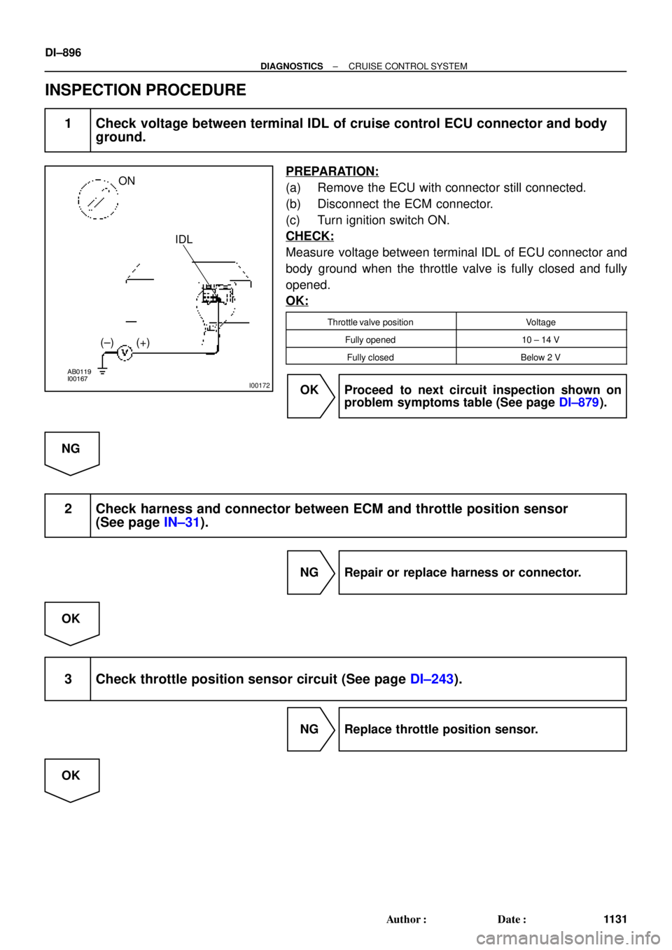
1 Check voltage between terminal IDL of cruise control ECU connector and body
ground.
PREPARATION:
(a) Remove the ECU with connector still connected.
(b) Disconnect the ECM connector.
(c) Turn ignition switch ON.
CHECK:
Measure voltage between terminal IDL of ECU connector and
body ground when the throttle valve is fully closed and fully
opened.
OK:
Throttle valve positionVoltage
Fully opened10 ± 14 V
Fully closedBelow 2 V
OK Proceed to next circuit inspection shown on
problem symptoms table (See page DI±879).
NG
2 Check harness and connector between ECM and throttle position sensor
(See page IN±31).
NG Repair or replace harness or connector.
OK
3 Check throttle position sensor circuit (See page DI±243).
NG Replace throttle position sensor.
OK