Page 3269 of 4770

I00266
Theft Deterrent ECU
TAIL
T3
11
G±R
B BJ/C J33
G±R
10
IG1
G±RA
AJ2
J/C
G±R 1C
6
2
3
Taillight Control Relay
1
5
TAIL81S
1C
9
1B
4 Instrument Panel J/B
B±R
Light
Failure
Sensor
Turn & Clearance
Light
1F9
F4
1
FL
BLOCK
FL MAIN
Battery
B±G ALT
± DIAGNOSTICSTHEFT DETERRENT SYSTEM
DI±849
1084 Author�: Date�:
Taillight Control Relay Circuit
CIRCUIT DESCRIPTION
When the theft deterrent system is activated, it causes the Tr in the ECU to switch ON and OFF at approxi-
mately 0.4 sec. intervals. This switches the taillight control relay ON and OFF, thus flashing the taillights (See
the wiring diagram below).
In this condition, if any of the following operations is done, the Tr in the ECU goes OFF and the taillight control
relay switches OFF, thus stopping the taillights flashing:
(1) Unlock the front LH or RH door with key.
(2) Turn the ignition switch to ACC or ON position.
(3) Unlock the doors with the wireless door lock control system.
(4) Wait for approximately 60 seconds.
(5) Push the panic switch of the wireless door lock control system.
WIRING DIAGRAM
DI06Y±06
Page 3271 of 4770
I01927
Theft Deterrent ECU
T4
13
IG B±R B
J17
C
J16B±R Instrument Panel J/B
8
1
ECU±IG
1
1B AM1
2
1K
4 B±Y AM1
2Ignition Switch
W
B±R
B±R 1
F9 ALT
FL BLOCK
F4
1
B±G
FL MAIN
Battery
1D
1K
IG1
± DIAGNOSTICSTHEFT DETERRENT SYSTEM
DI±851
1086 Author�: Date�:
Ignition Switch Circuit
CIRCUIT DESCRIPTION
When the ignition switch is turned to the ACC position, battery positive voltage is applied to the terminal ACC
of the ECU. Also, if the ignition switch is turned to the ON position, battery positive voltage is applied to the
terminals ACC and IG of the ECU. When the battery positive voltage is applied to the terminal ACC of the
ECU while the theft deterrent system is activated, the warning stops. Furthermore, power supplied from the
terminals ACC and IG of the ECU is used as power for the door courtesy switch, and position switch, etc.
WIRING DIAGRAM
DI06Z±06
Page 3272 of 4770
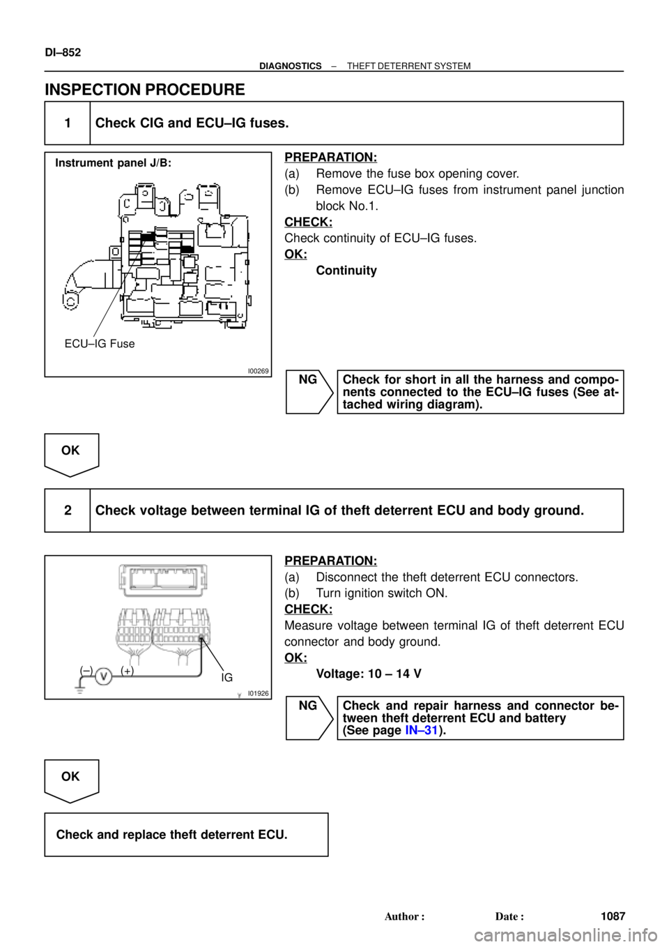
I00269
Instrument panel J/B:
ECU±IG Fuse
I01926
IG (+) (±)
DI±852
± DIAGNOSTICSTHEFT DETERRENT SYSTEM
1087 Author�: Date�:
INSPECTION PROCEDURE
1 Check CIG and ECU±IG fuses.
PREPARATION:
(a) Remove the fuse box opening cover.
(b) Remove ECU±IG fuses from instrument panel junction
block No.1.
CHECK:
Check continuity of ECU±IG fuses.
OK:
Continuity
NG Check for short in all the harness and compo-
nents connected to the ECU±IG fuses (See at-
tached wiring diagram).
OK
2 Check voltage between terminal IG of theft deterrent ECU and body ground.
PREPARATION:
(a) Disconnect the theft deterrent ECU connectors.
(b) Turn ignition switch ON.
CHECK:
Measure voltage between terminal IG of theft deterrent ECU
connector and body ground.
OK:
Voltage: 10 ± 14 V
NG Check and repair harness and connector be-
tween theft deterrent ECU and battery
(See page IN±31).
OK
Check and replace theft deterrent ECU.
Page 3273 of 4770
I08429
Instrument Panel J/B Key Unlock
Warning SwitchTheft Deterrent ECU
W±B6
KSW
L±BT4 B
J9 B
J9J/C
L±B
L±B
A
J11
J/C
IG W±B 7
1J 3
1M 215
1M7
1D
Instrument Panel J/B
± DIAGNOSTICSTHEFT DETERRENT SYSTEM
DI±853
1088 Author�: Date�:
Key Unlock Warning Switch Circuit
CIRCUIT DESCRIPTION
The key unlock warning switch goes ON when the ignition key is inserted in the key cylinder and goes OFF
when the ignition key is removed.
The ECU operates the key confinement prevention function while the key unlock warning switch is ON.
WIRING DIAGRAM
DI070±06
Page 3276 of 4770
 (±)
I00270
21
DI±856
± DIAGNOSTICSTHEFT DETERRENT SYSTEM
1091 Author�: Date�:
INSPECTION PROCEDURE
1 Check voltage between terminal 1 of luggage compartment door key lo")
AB0119
I00271I00277
ON
1
(+) (±)
I00270
21
DI±856
± DIAGNOSTICSTHEFT DETERRENT SYSTEM
1091 Author�: Date�:
INSPECTION PROCEDURE
1 Check voltage between terminal 1 of luggage compartment door key lock and
unlock switch connector and body ground.
PREPARATION:
(a) Remove luggage compartment door trim.
(b) Turn ignition switch ON.
CHECK:
Measure voltage between terminal 1 of luggage compartment
door key lock and unlock switch connector and body ground,
when the key is turned to the unlock side and not turned respec-
tively.
OK:
Key operationVoltage
Turned to the unlock side0 V
Not turnedBattery positive voltage
OK Check and replace theft deterrent ECU.*1
NG
2 Check luggage compartment door key lock and unlock switch.
PREPARATION:
Disconnect luggage compartment door key lock and unlock
switch connector.
CHECK:
Check continuity between terminals 1 and 2, when the key is
turned to the unlock side and not turned respectively.
OK:
Key operationTester connectionSpecified condition
Turned to unlock1 ± 2Continuity
Not turned±No continuity
NG Repair or replace luggage compartment door
key lock and unlock switch.
OK
Page 3290 of 4770

I00279CRUISE MAIN Indicator Light
DI1KS±03
BE4034
Indicator light
1.5 sec.0.5 sec.
ON
OFF
I00169
DLC2
Tc E 1
DI±870
± DIAGNOSTICSCRUISE CONTROL SYSTEM
1105 Author�: Date�:
PRE±CHECK
1. DIAGNOSIS SYSTEM
(a) Check the indicator.
(1) Turn the ignition switch ON.
(2) Check that the CRUISE MAIN indicator light comes
ON when the cruise control main switch is turned
ON, and that the indicator light goes OFF when the
main switch is turned OFF.
HINT:
If the indicator check result is not normal, proceed to trouble-
shooting (See page BE±2) for the combination meter section.
(b) Check the DTC.
HINT:
If a malfunction occurs in the No. 1 vehicle speed sensor or ac-
tuator, etc. during cruise control driving, the ECU actuates
AUTO CANCEL of the cruise control and turns on and off the
CRUISE MAIN indicator light to inform the driver of a malfunc-
tion. At the same time, the malfunction is stored in memory as
a DTC.
(c) Output of DTC using diagnosis check wire.
(1) Turn the ignition switch ON.
(2) Using SST, connect terminals Tc and E
1 of DLC2.
SST 09843±18020
(3) Read the DTC on the CRUISE MAIN indicator light.
Page 3294 of 4770

(2)
(1)
No.Operation MethodCRUISE MAIN Indicator Light
Blinking PatternDiagnosis
1 Turn SET/COAST switch ON
2Turn RES/ACC switch ON
3Turn CANCEL switch ON
Turn stop light switch ON
Depress")
N17520
(1)
(2)
(1)
No.Operation MethodCRUISE MAIN Indicator Light
Blinking PatternDiagnosis
1 Turn SET/COAST switch ON
2Turn RES/ACC switch ON
3Turn CANCEL switch ON
Turn stop light switch ON
Depress brake pedal
Turn PNP switch OFF
(Shift to except D position)
4Drive at about 40 km/h
(25 mph)or higher
Drive at about 40 km/h
(25 mph) or below
LightON
OFF
LightON
OFF
LightON
OFFSwitch ON
Switch OFF
LightON
OFFSwitch OFF
Switch ONSET/COAST switch circuit
is normal
RES/ACC switch circuit
is normal
CANCEL switch circuit
is normal
Stop light switch circuit
is normal
PNP switch circuit is
normal
Vehicle Speed Sensor is
normal
LightON
OFF LightON
OFF
1sec.
0.25 sec.0.25 sec.
Turn clutch switch OFF
(Depress clutch pedal)Clutch switch circuit
is normal
DI±874
± DIAGNOSTICSCRUISE CONTROL SYSTEM
1109 Author�: Date�:
5. INPUT SIGNAL CHECK
HINT:
(1) For check No.1 ~ No.3
�Turn ignition switch ON.
(2) For check No.4
�Jack up the vehicle.
�Start the engine.
�Shift to D position.
(a) Pull the control switch to SET/COAST or RES/ACC posi-
tion and hold it down or up (1).
(b) Push the main switch ON (2).
(c) Check that the CRUISE MAIN indicator light blinks twice
or 3 times repeatedly after 3 seconds.
(d) Turn the SET/COAST or RES/ACC switch OFF.
(e) Operate each switch as listed in the table below.
(f) Read the blinking pattern of the CRUISE MAIN indicator
light.
(g) After performing the check, turn the main switch OFF.
HINT:
When 2 or more signals are input to the ECU, the lowest num-
bered code will be displayed first.
Page 3297 of 4770
Wiring ColorConditionSTD Voltage (V)
STP± e GND GWWBDepress brake pedal1")
DI1KT±06
I00293
C15
± DIAGNOSTICSCRUISE CONTROL SYSTEM
DI±877
111 2 Author�: Date�:
TERMINALS OF ECU
Symbols (Terminals No.)Wiring ColorConditionSTD Voltage (V)
STP± e GND GWWBDepress brake pedal10 ± 16 VSTP e GND
(C15±2 e C15±16)G±W e W±BRelease brake pedalBelow 1 V
DGND (C15 3C15 16)BRWBShift to positions except DBelow 1 VD e GND (C15±3 e C15±16)B±R e W±BShift to D position10 ± 16 V
PIGND (C15 4C15 16)OWB
Ignition switch ON
Cruise control main switch ONBelow 1.2 V
PI e GND (C15±4 e C15±16)O e W±BIgnition switch ON
Cruise control main switch OFF10 ± 16 V
TCGNDIgnition switch ON10 ± 16 VTC e GND
(C15±5 e C15±16)LG±R e W±BIgnition switch ON
Connect terminals Tc and E1 of diagnostic check connectorBelow 1 V
ECT e GND LBWB
During driving
Gear position 3rd10 ± 16 VECT e GND
(C15±6 e C15±16)L±B e W±BDuring driving
Gear position O/DBelow 1 V
MC e GND RBWB
During cruise control driving
COAST switch held ON9 ± 15 VMC e GND
(C15±7 e C15±16)R±B e W±BDuring cruise control driving
ACC switch held ONBelow 1 V
L e GND GBWBDuring cruise control driving9 ± 15 VL e GND
(C15±8 e C15±16)G±B e W±BExcept during cruise control drivingBelow 1 V
B e GND
(C15±9 e C15±16)B±R e W±BIgnition switch ON10 ± 16 V
Ignition switch ON10 ± 16 V
CCSGND
Ignition switch ON
CANCEL switch held ON4.2 ± 8.8 V
CCS e GND
(C15±10 e C15±16)W e W±BIgnition switch ON
SET/COAST switch held ON2.5 ± 6.3 V
Ignition switch ON
RES/ACC switch held ON0.8 ± 3.7 V