Page 3334 of 4770
I00290
Cruise Control ECU
4
PI
O D DJ/C
O IG25
O 10
7
R±L D DJ/C
R±L
Instrument Panel J/B
2
1D
1K1
B±Y4IG1AM1 Ignition Switch
2
W
Instrument Panel J/B
AM1 GAUGE
2
1K 1
1B
B±R 1
ALT FL BLOCK
1
B±G
FL MAIN
BatteryCRUISE MAIN
Indicator Light
(in Combination Meter)
C15
J2
C10
C10 J4
F9
F4 DI±914
± DIAGNOSTICSCRUISE CONTROL SYSTEM
1149 Author�: Date�:
CRUISE MAIN Indicator Light Circuit
CIRCUIT DESCRIPTION
When the cruise control main switch is turned ON, CRUISE MAIN indicator light lights up.
WIRING DIAGRAM
DI090±17
Page 3335 of 4770
AB0119
I00144
I00178
ON
PI
(±) (+)
± DIAGNOSTICSCRUISE CONTROL SYSTEM
DI±915
1150 Author�: Date�:
INSPECTION PROCEDURE
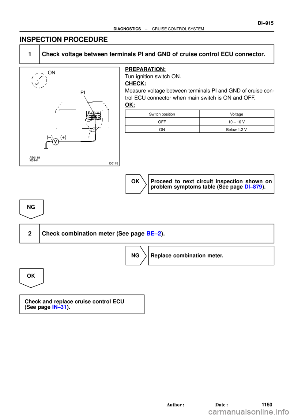
1 Check voltage between terminals PI and GND of cruise control ECU connector.
PREPARATION:
Tun ignition switch ON.
CHECK:
Measure voltage between terminals PI and GND of cruise con-
trol ECU connector when main switch is ON and OFF.
OK:
Switch positionVoltage
OFF10 ± 16 V
ONBelow 1.2 V
OK Proceed to next circuit inspection shown on
problem symptoms table (See page DI±879).
NG
2 Check combination meter (See page BE±2).
NG Replace combination meter.
OK
Check and replace cruise control ECU
(See page IN±31).
Page 3337 of 4770
AB0119
I00169
I00179
ON
TC E1
± DIAGNOSTICSCRUISE CONTROL SYSTEM
DI±917
1152 Author�: Date�:
INSPECTION PROCEDURE
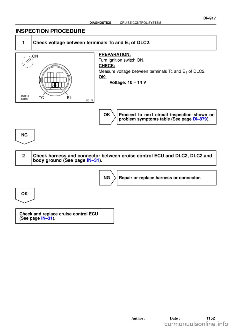
1 Check voltage between terminals Tc and E1 of DLC2.
PREPARATION:
Turn ignition switch ON.
CHECK:
Measure voltage between terminals Tc and E1 of DLC2.
OK:
Voltage: 10 ± 14 V
OK Proceed to next circuit inspection shown on
problem symptoms table (See page DI±879).
NG
2 Check harness and connector between cruise control ECU and DLC2, DLC2 and
body ground (See page IN±31).
NG Repair or replace harness or connector.
OK
Check and replace cruise control ECU
(See page IN±31).
Page 3341 of 4770
 Description
ECM controls the function of i")
S05335
TOYOTA hand±held tester
DLC3
DI1KG±04
N09214
± DIAGNOSTICSENGINE IMMOBILISER SYSTEM
DI±921
1156 Author�: Date�:
PRE±CHECK
1. DIAGNOSIS SYSTEM
(a) Description
ECM controls the function of immobiliser on this vehicle.
Data of the immobiliser or DTC can be read form DLC3 of
the vehicle. When a trouble occurs in immobiliser, MIL
does not light ON but DTC inspection is performed.
Therefore when there seems to be a trouble with immobi-
liser, use TOYOTA hand±held tester or SST to check and
troubleshoot it.
(b) DLC3 INSPECTION
The vehicle's ECM uses ISO 9141±2 for communication.
The terminal arrangement of DLC3 complies with
SAEJ1962 and matches the ISO 9141±2 format.
Tester connectionconditionSpecified condition
7 (Bus � Line) ± 5 (Signal ground)During communicationPulse generation
4 (chassis Ground) ± BodyAlways1 W or less
5 (Signal Ground) ± BodyAlways1 W or less
16 (B+) ± BodyAlways9 ± 14 V
HINT:
If your display shows ºUNABLE TO CONNECT TO VEHICLEº
when you have connected the cable of OBD ll scan tool or TOY-
OTA hand±held tester to DLC3, turned the ignition switch ON
and operated the scan tool, there is a problem on the vehicle
side or tool side.
(1) If communication is normal when the tool is con-
nected to another vehicle, inspect DLC3 on the orig-
inal vehicle.
(2) If communication is still impossible when the tool is
connected to another vehicle, the problem is prob-
ably in the tool itself, so consult the Service Depart-
ment listed in the tool's instruction manual.
Page 3342 of 4770
 Check the DTC (Using TOYOTA hand±held tester)
(1")
F02201
DLC1
TE1E1
BR3904
Normal code
0.25 Sec. 0.25 Sec. DI±922
± DIAGNOSTICSENGINE IMMOBILISER SYSTEM
1157 Author�: Date�:
2. INSPECT DIAGNOSIS
(a) Check the DTC (Using TOYOTA hand±held tester)
(1) Prepare the OBD ll scan tool (complying with SAEJ
1978) or TOYOTA hand±held tester.
(2) Connect the OBD ll scan tool or TOYOTA hand±
held tester to DLC3 under the instrument panel low-
er pad.
(3) Turn the ignition switch ON and turn the OBD ll scan
tool or TOYOTA hand±held tester switch ON.
(4) Use the OBD ll scan tool or TOYOTA hand±held
tester to check the DTCs and freeze frame data;
note them down. (For operating instructions, see
the OBD ll scan tool's instruction book.)
(5) See page DI±924 to confirm the details of the DTCs.
(b) Check the DTC (Using diagnosis check wire)
(1) Turn ignition switch ON.
(2) Using SST, connect between terminals 8 (TE1) and
3 (E1) of DLC1.
SST 09843±18040
(3) Read the diagnostic trouble code from malfunction
indicator lamp.
HINT:
�If a diagnostic trouble code is not output, check the Tc ter-
minal circuit .
�ECM controls the immobiliser function on this vehicle,
DTC is out put with DTC of engine.
As an example, the blinking patterns for codes; normal, 12 and
99 are as shown in the illustration.
Page 3346 of 4770
DI1KJ±04
D01054
E7 E8E10
E11 E9 DI±926
± DIAGNOSTICSENGINE IMMOBILISER SYSTEM
1161 Author�: Date�:
TERMINALS OF ECM
5S±FE engine:
Symbols (Terminals No.)Wiring ColorConditionSTD Voltage (V)
CODE ± E1
(E10±8 e E9±24)G±W e BRIgnition Switch ON10 ± 14
TXCK ± E1
(E10±9 e E9±24)L±Y e BRIgnition Switch ON10 ± 14
RXCK ± E1
(E10±3 e E9±24)R±L e BRIgnition Switch ON10 ± 14
1MZ±FE engine:
Symbols (Terminals No.)Wiring ColorConditionSTD Voltage (V)
CODE ± E1
(E9±4 e E10±17)G±W e BRIgnition Switch ON10 ± 14
TXCK ± E1
(E9±10 e E10±17)L±Y e BRIgnition Switch ON10 ± 14
RXCK ± E1
(E9±5 e E10±17)R±L e BRIgnition Switch ON10 ± 14
Page 3385 of 4770
EC0AW±01
S05477
DisconnectOhmmeter
E2 VC
B01480
E2(±)
VC(+)
± EMISSION CONTROL (1MZ±FE)EXHAUST GAS RECIRCULATION (EGR) SYSTEM
EC±11
1426 Author�: Date�:
EXHAUST GAS RECIRCULATION
(EGR) SYSTEM
INSPECTION
1. INSPECT EGR SYSTEM (See page DI±358)
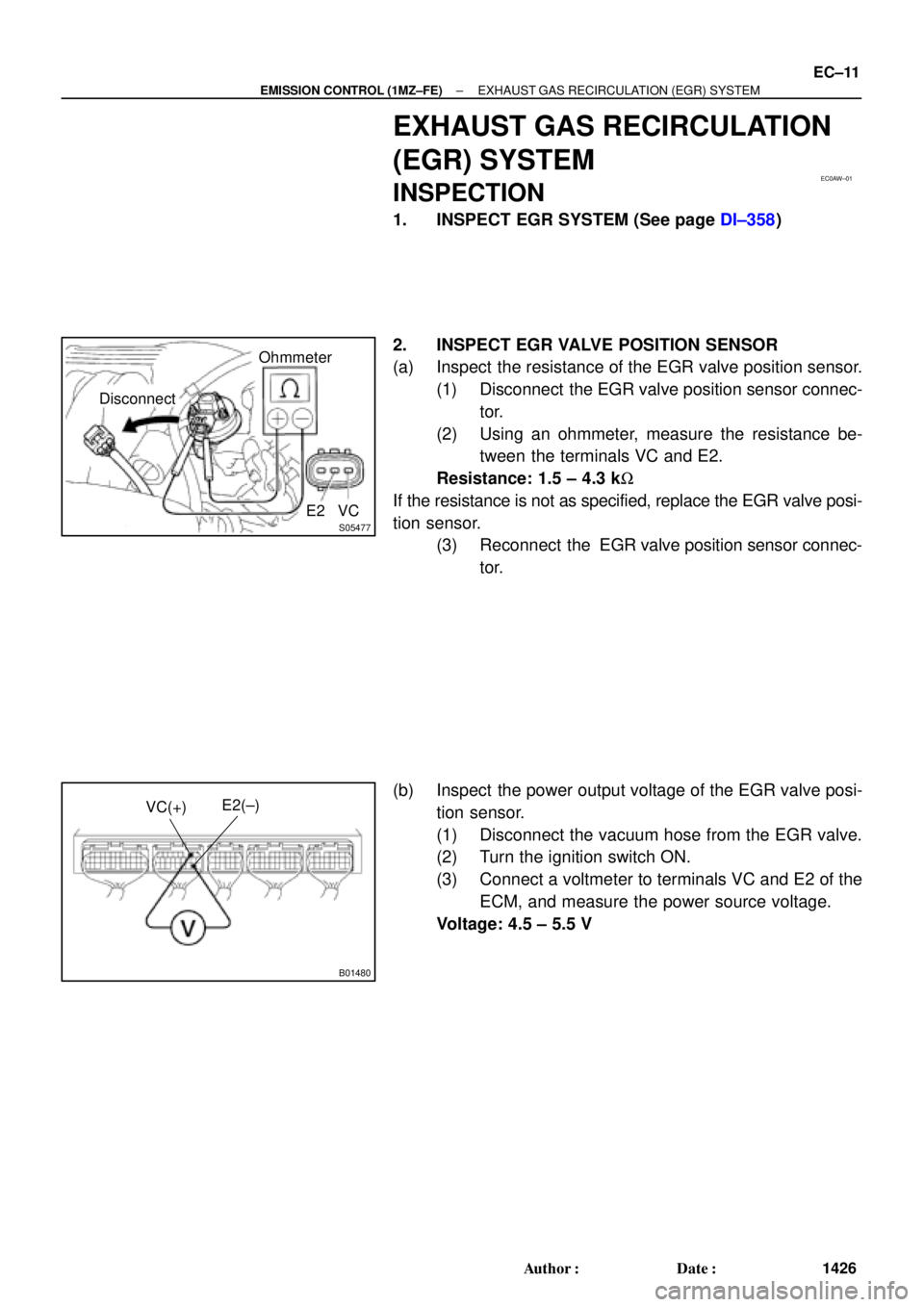
2. INSPECT EGR VALVE POSITION SENSOR
(a) Inspect the resistance of the EGR valve position sensor.
(1) Disconnect the EGR valve position sensor connec-
tor.
(2) Using an ohmmeter, measure the resistance be-
tween the terminals VC and E2.
Resistance: 1.5 ± 4.3 kW
If the resistance is not as specified, replace the EGR valve posi-
tion sensor.
(3) Reconnect the EGR valve position sensor connec-
tor.
(b) Inspect the power output voltage of the EGR valve posi-
tion sensor.
(1) Disconnect the vacuum hose from the EGR valve.
(2) Turn the ignition switch ON.
(3) Connect a voltmeter to terminals VC and E2 of the
ECM, and measure the power source voltage.
Voltage: 4.5 ± 5.5 V
Page 3393 of 4770
CO/HC
EM±1
1173 Author�: Date�:
CO/HC
INSPECTION
HINT:
This check is used only to determine whether or not the idle CO/
HC complies with regu")
EM07X±05
S04994
CO/HC Meter
± ENGINE MECHANICAL (5S±FE)CO/HC
EM±1
1173 Author�: Date�:
CO/HC
INSPECTION
HINT:
This check is used only to determine whether or not the idle CO/
HC complies with regulations.
1. INITIAL CONDITIONS
(a) Engine at normal operating temperature
(b) Air cleaner installed
(c) All pipes and hoses of air induction system connected
(d) All accessories switched OFF
(e) All vacuum lines properly connected
HINT:
All vacuum hoses for EGR system, etc. should be properly con-
nected.
(f) SFI system wiring connectors fully plugged
(g) Ignition timing checked correctly
(h) Transmission in neutral position
(i) Tachometer and CO/HC meter calibrated by hand
2. START ENGINE
3. RACE ENGINE AT 2,500 RPM FOR APPROX. 180 SE-
CONDS
4. INSERT CO/HC METER TESTING PROBE AT LEAST
40 cm (1.3 ft) INTO TAILPIPE DURING IDLING
5. IMMEDIATELY CHECK CO/HC CONCENTRATION AT
IDLE AND/OR 2,500 RPM
Complete the measuring within 3 minutes.
HINT:
When performing the 2 mode (2,500 rpm and idle) test, follow
the measurement order prescribed by the applicable local regu-
lations.