Page 3320 of 4770
AB0119
I00142
I00173
ON
STP±
(±) (+)
DI±900
± DIAGNOSTICSCRUISE CONTROL SYSTEM
1135 Author�: Date�:
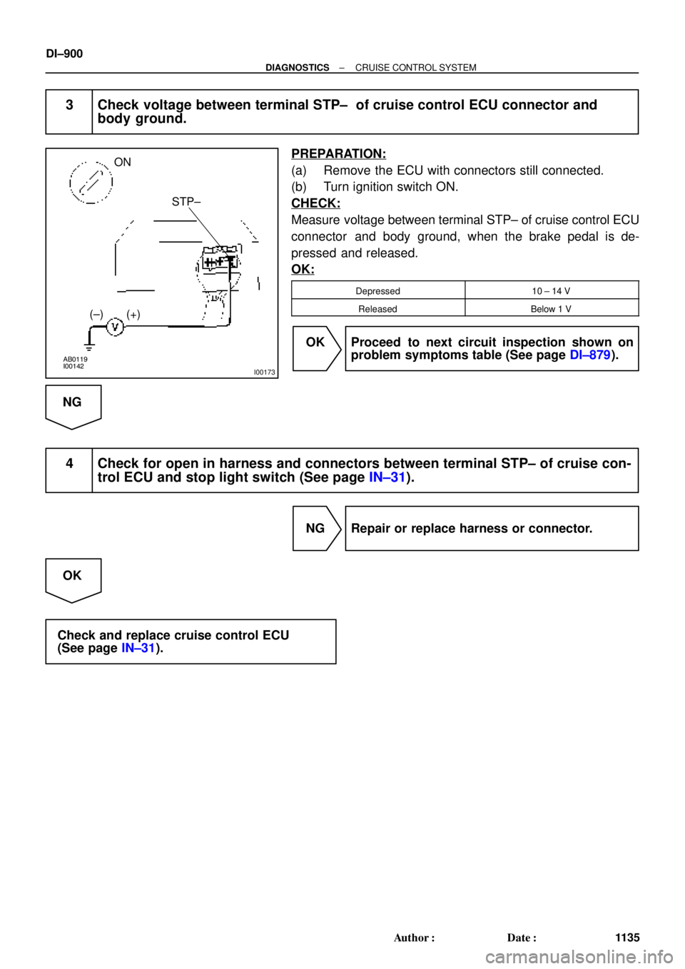
3 Check voltage between terminal STP± of cruise control ECU connector and
body ground.
PREPARATION:
(a) Remove the ECU with connectors still connected.
(b) Turn ignition switch ON.
CHECK:
Measure voltage between terminal STP± of cruise control ECU
connector and body ground, when the brake pedal is de-
pressed and released.
OK:
Depressed10 ± 14 V
ReleasedBelow 1 V
OK Proceed to next circuit inspection shown on
problem symptoms table (See page DI±879).
NG
4 Check for open in harness and connectors between terminal STP± of cruise con-
trol ECU and stop light switch (See page IN±31).
NG Repair or replace harness or connector.
OK
Check and replace cruise control ECU
(See page IN±31).
Page 3322 of 4770
AB0119
I00143
I00174
ON
O/D
(±) (+)
DI±902
± DIAGNOSTICSCRUISE CONTROL SYSTEM
1137 Author�: Date�:
INSPECTION PROCEDURE
1 Check operation of overdrive.
PREPARATION:
Test drive after engine warms up.
CHECK:
Check that overdrive ON e OFF occurs by operation of OD switch ON±OFF.
NG Check and repair electronically controlled
transmission (See page DI±389).
OK
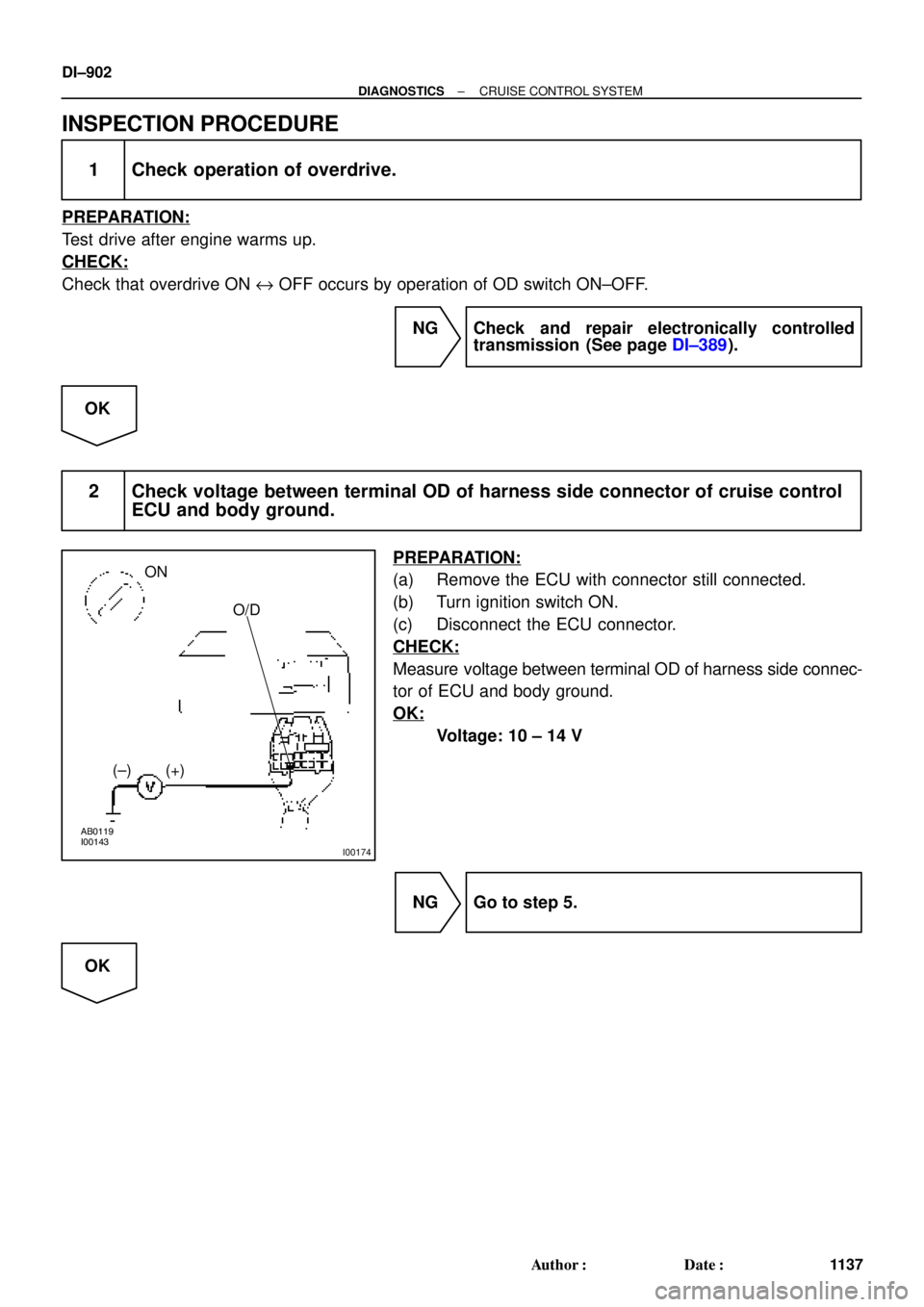
2 Check voltage between terminal OD of harness side connector of cruise control
ECU and body ground.
PREPARATION:
(a) Remove the ECU with connector still connected.
(b) Turn ignition switch ON.
(c) Disconnect the ECU connector.
CHECK:
Measure voltage between terminal OD of harness side connec-
tor of ECU and body ground.
OK:
Voltage: 10 ± 14 V
NG Go to step 5.
OK
Page 3324 of 4770
I08433
Cruise Control ECU
Instrument Panel J/B
Clutch Switch
PNP Switch GAUGE
1K
D 3 J29
J/C
J/C
J21 (5S±FE)
J24 (1MZ±FE) B±Y1JC15 For M/T
J/C
B±R A
A
A B±R
R±L R±L
2
1 D
J27 F
J28
F J28
R±L
R±L 2
II2
A
A
R±L210
B±R9
II2For A/T
FL BLOCK IG1
Battery Ignition Switch
2
4AM1
Instrument Panel J/B
AM1
1B1
1K2W
B±R
F91
F41
ALT
B±G
FL MAIN 11 DI±904
± DIAGNOSTICSCRUISE CONTROL SYSTEM
1139 Author�: Date�:
Park/Neutral Position Switch Circuit
CIRCUIT DESCRIPTION
When the shift position is except D, a signal is sent from the park/neutral position switch to the ECU. When
this signal is input during cruise control driving, the ECU cancels the cruise control.
WIRING DIAGRAM
DI08V±11
Page 3326 of 4770
AB0119
I00139
I00175
ON
D
(±) (+)
DI±906
± DIAGNOSTICSCRUISE CONTROL SYSTEM
1141 Author�: Date�:
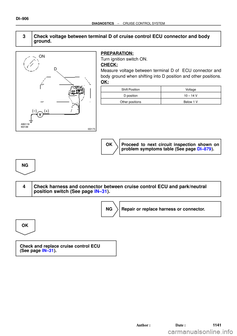
3 Check voltage between terminal D of cruise control ECU connector and body
ground.
PREPARATION:
Turn ignition switch ON.
CHECK:
Measure voltage between terminal D of ECU connector and
body ground when shifting into D position and other positions.
OK:
Shift PositionVoltage
D position10 ± 14 V
Other positionsBelow 1 V
OK Proceed to next circuit inspection shown on
problem symptoms table (See page DI±879).
NG
4 Check harness and connector between cruise control ECU and park/neutral
position switch (See page IN±31).
NG Repair or replace harness or connector.
OK
Check and replace cruise control ECU
(See page IN±31).
Page 3328 of 4770
AB0119
I00139
I00175
ON
D
(±) (+)
DI±908
± DIAGNOSTICSCRUISE CONTROL SYSTEM
1143 Author�: Date�:
3 Check voltage between terminal D of cruise control ECU and body ground.
PREPARATION:
Turn ignition switch ON.
CHECK:
Measure voltage between terminal D of cruise control ECU con-
nector and body ground when clutch pedal is depressed and
pushed in.
OK:
Shift PositionVoltage
Clutch pedal depressed10 ± 14 V
Clutch pedal pushed inBelow 1 V
OK Proceed to next circuit inspection shown on
problem symptoms table (See page DI±879).
NG
4 Check for open in harness and connector between ECU and GAUGE fuse
(See page IN±31).
NG Repair or replace harness or connector.
OK
Check and replace cruise control ECU
(See page IN±31).
Page 3329 of 4770
I08434
Instrument Panel J/B
Ignition Switch
ECU±IG
B 9 J12
J/C
B±YC15
B±R C
C
GND
IG1
2
B±R IG1
Battery24
AM1
Instrument Panel J/B
AM1 1K1
W
B±GF9
F41
W±B
FL MAINCruise Control ECU
1J9
B±R
1K
1B1
16
C15
W±B
W±BJ8A
J7AJ/C
1J8
1J7Instrument Panel J/B
A J11
J/C FL BLOCK
ALT
± DIAGNOSTICSCRUISE CONTROL SYSTEM
DI±909
1144 Author�: Date�:
ECU Power Source Circuit
CIRCUIT DESCRIPTION
The ECU power source supplies power to the actuator and sensors, etc, when terminal GND and the cruise
control ECU case are grounded.
WIRING DIAGRAM
DI08X±11
Page 3330 of 4770
I00157
Instrument panel junction block No.1:
ECU±IG
Fuse
AB0119
I00147
I00176
ON
GND
(±) (+)B
DI±910
± DIAGNOSTICSCRUISE CONTROL SYSTEM
1145 Author�: Date�:
INSPECTION PROCEDURE
1 Check ECU±IG fuse.
PREPARATION:
Remove the ECU±IG fuse from instrument panel junction block
No.1.
CHECK:
Check continuity of ECU±IG fuse.
OK:
Continuity
NG Check for short in all the harness and compo-
nents connected to ECU±IG fuse.
OK
2 Check voltage between terminals B and GND of cruise control ECU connector.
PREPARATION:
(a) Remove the ECU with connector still connected.
(b) Turn ignition switch ON.
CHECK:
Measure voltage between terminals B and GND of ECU con-
nector.
OK:
10 ± 14 V
OK Proceed to next circuit inspection shown on
problem symptoms table (See page DI±879).
NG
Page 3332 of 4770
AB0119
I00145
I00177
ON
CMS
(±) (+)
DI±912
± DIAGNOSTICSCRUISE CONTROL SYSTEM
1147 Author�: Date�:
Main Switch Circuit (Cruise Control Switch)
CIRCUIT DESCRIPTION
When the cruise control main switch is turned OFF, the cruise control does not operate.
WIRING DIAGRAM
See page DI±892.
INSPECTION PROCEDURE
1 Check voltage between terminal CMS of cruise control ECU connector and body
ground.
PREPARATION:
(a) Remove the ECU with connector still connected.
(b) Turn ignition switch ON.
CHECK:
Measure voltage between terminal CMS of cruise control ECU
connector when main switch is held ON and OFF.
OK:
Main switchVoltage
OFF10 ± 14 V
ONBelow 0.5 V
OK Proceed to next circuit inspection shown on
problem symptoms table (See page DI±879).
NG
DI08Z±16

J24 (1MZ±FE) B±Y1JC15 For M/T
J/C
B±R A
A
A B±R
R±L R±L
2
1 D
J27 F
J28
F J28
R±L
R")