Page 3540 of 4770

P20049Gasket
A05077
Clamp
Clamp
Clamp
S04786
EM±34
± ENGINE MECHANICAL (1MZ±FE)CYLINDER HEAD
1320 Author�: Date�:
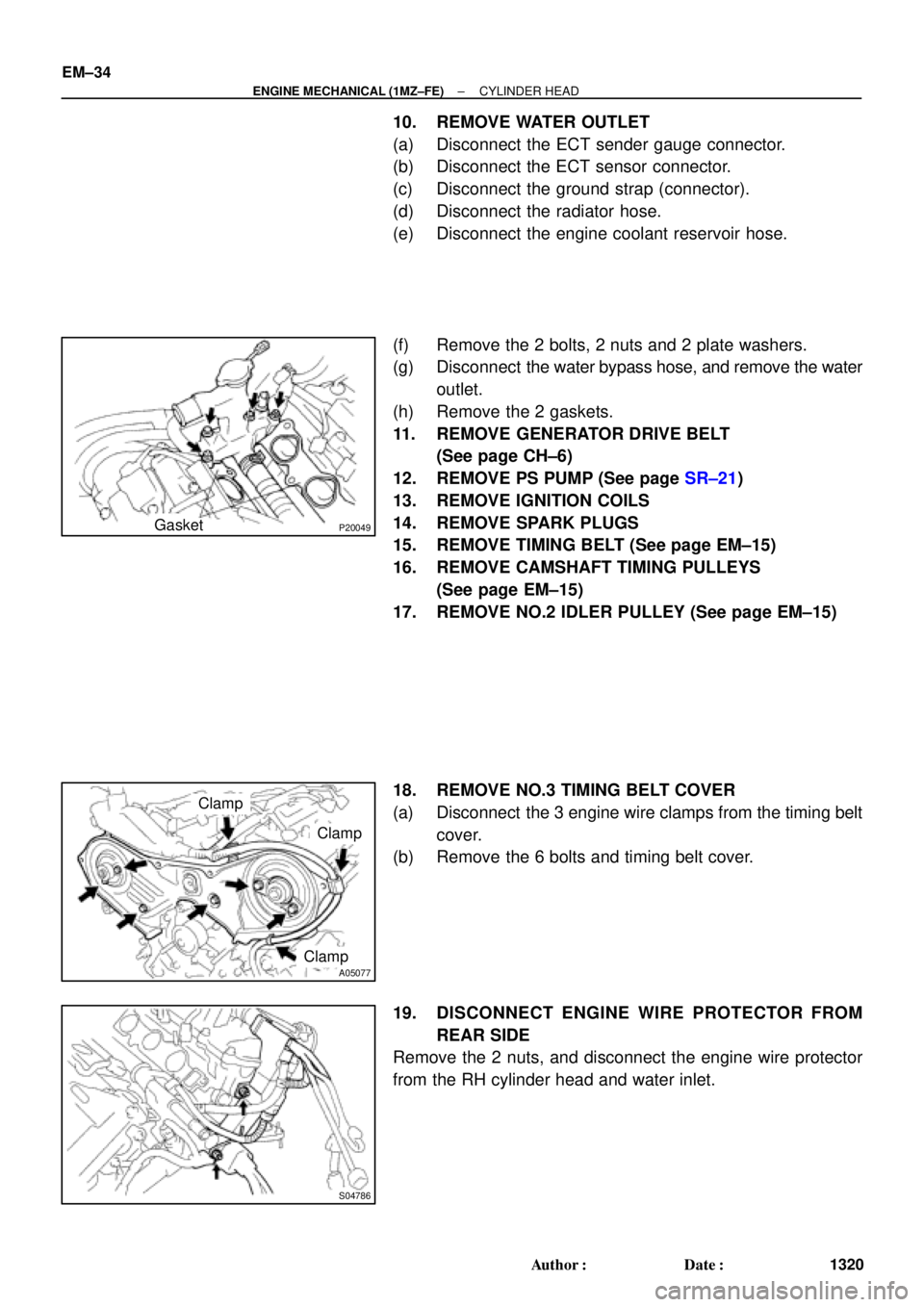
10. REMOVE WATER OUTLET
(a) Disconnect the ECT sender gauge connector.
(b) Disconnect the ECT sensor connector.
(c) Disconnect the ground strap (connector).
(d) Disconnect the radiator hose.
(e) Disconnect the engine coolant reservoir hose.
(f) Remove the 2 bolts, 2 nuts and 2 plate washers.
(g) Disconnect the water bypass hose, and remove the water
outlet.
(h) Remove the 2 gaskets.
11. REMOVE GENERATOR DRIVE BELT
(See page CH±6)
12. REMOVE PS PUMP (See page SR±21)
13. REMOVE IGNITION COILS
14. REMOVE SPARK PLUGS
15. REMOVE TIMING BELT (See page EM±15)
16. REMOVE CAMSHAFT TIMING PULLEYS
(See page EM±15)
17. REMOVE NO.2 IDLER PULLEY (See page EM±15)
18. REMOVE NO.3 TIMING BELT COVER
(a) Disconnect the 3 engine wire clamps from the timing belt
cover.
(b) Remove the 6 bolts and timing belt cover.
19. DISCONNECT ENGINE WIRE PROTECTOR FROM
REAR SIDE
Remove the 2 nuts, and disconnect the engine wire protector
from the RH cylinder head and water inlet.
Page 3572 of 4770

A05194
L = 133 mm (5.24 in.)
L = 180 mm (7.09 in.)L = 72 mm (2.83 in.)
L = 335 mm (13.19 in.)L = 180 mm
(7.09 in.)
L = Length Join
LineJoin
Line
Z14262New Gasket
A01808
8
6
5
4
3
2
1
9
10
7
11
EM±66
± ENGINE MECHANICAL (1MZ±FE)CYLINDER HEAD
1352 Author�: Date�: �
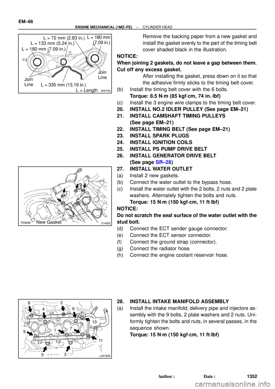
Remove the backing paper from a new gasket and
install the gasket evenly to the part of the timing belt
cover shaded black in the illustration.
NOTICE:
When joining 2 gaskets, do not leave a gap between them.
Cut off any excess gasket.
�After installing the gasket, press down on it so that
the adhesive firmly sticks to the timing belt cover.
(b) Install the timing belt cover with the 6 bolts.
Torque: 8.5 N´m (85 kgf´cm, 74 in.´lbf)
(c) Install the 3 engine wire clamps to the timing belt cover.
20. INSTALL NO.2 IDLER PULLEY (See page EM±21)
21. INSTALL CAMSHAFT TIMING PULLEYS
(See page EM±21)
22. INSTALL TIMING BELT (See page EM±21)
23. INSTALL SPARK PLUGS
24. INSTALL IGNITION COILS
25. INSTALL PS PUMP DRIVE BELT
26. INSTALL GENERATOR DRIVE BELT
(See page SR±28)
27. INSTALL WATER OUTLET
(a) Install 2 new gaskets.
(b) Connect the water outlet to the bypass hose.
(c) Install the water outlet with the 2 bolts, 2 nuts and 2 plate
washers. Alternately tighten the bolts and nuts.
Torque: 15 N´m (150 kgf´cm, 11 ft´lbf)
NOTICE:
Do not scratch the seal surface of the water outlet with the
stud bolt.
(d) Connect the ECT sender gauge connector.
(e) Connect the ECT sensor connector.
(f) Connect the ground strap (connector).
(g) Connect the radiator hose.
(h) Connect the engine coolant reservoir hose.
28. INSTALL INTAKE MANIFOLD ASSEMBLY
(a) Install the intake manifold, delivery pipe and injectors as-
sembly with the 9 bolts, 2 plate washers and 2 nuts. Uni-
formly tighten the bolts and nuts, in several passes, in the
sequence shown.
Torque: 15 N´m (150 kgf´cm, 11 ft´lbf)
Page 3619 of 4770

RS02P±03
H03287
W03509
RS±28
± SUPPLEMENTAL RESTRAINT SYSTEMFRONT PASSENGER AIRBAG ASSEMBLY
2163 Author�: Date�:
2001 CAMRY (RM819U)
REMOVAL
NOTICE:
�If the wiring connector of the SRS is disconnected
and the ignition switch is in ON or ACC position, DTCs
will be recorded.
�Never use the airbag parts from another vehicle.
When replacing parts, replace them with new parts.
HINT:
For step 2 to 4, refer to page BO±75.
1. DISCONNECT AIRBAG CONNECTOR
(a) Remove the glove compartment door finish plate inside
the glove compartment box.
NOTICE:
When handling the airbag connector, take care not to dam-
age the airbag wire harness.
(b) Pull up the connector.
(c) Disconnect the front passenger airbag connector.
2. REMOVE FRONT DOOR SCUFF PLATE
3. REMOVE COWL SIDE TRIM
4. REMOVE GLOVE COMPARTMENT BOX
5. REMOVE FRONT PASSENGER AIRBAG ASSEMBLY
Remove the 2 bolts, 4 nuts and front passenger airbag assem-
bly.
CAUTION:
�Do not store the front passenger airbag assembly
with the airbag deployment side facing downward.
�Never disassemble the front passenger airbag as-
sembly.
Page 3640 of 4770
BE0A4±04
I21685
E/G Room J/B No.2
� HEAD LH Fuse
(w/o Daytime Running Light)
� HEAD RH Fuse
(w/o Daytime Running Light)
� HEAD LH (UPR) Fuse
(w/ Daytime Running Light)
� HEAD RH (UPR) Fuse
(w/ Daytime Running Light)
� DOME Fuse
� ECU±B Fuse
� Headlight Control Relay
E/G Room R/B No.2
(w/ Daytime Running Light)
� HEAD LH (LWR) Fuse
� HEAD RH (LWR) Fuse
� DRL No.2 Fuse
� Daytime Running Light Relay No.2
� Daytime Running Light Relay No.3
� Daytime Running Light Relay No.4
Headlight
Instrument Panel J/B No.1
� GAUGE Fuse
� TAIL Fuse
� Taillight Control Relay
� Integration Relay
Daytime Running
Light Relay (Main)Ignition Switch
Combination Switch
� Light Control Switch
� Headlight Dimmer Switch
Door Courtesy Switch
Light Failure Sensor
Taillight
Automatic Light
Control Sensor
BE±22
± BODY ELECTRICALHEADLIGHT AND TAILLIGHT SYSTEM
2232 Author�: Date�:
2001 CAMRY (RM819U)
HEADLIGHT AND TAILLIGHT SYSTEM
LOCATION
Page 3643 of 4770

Z08523
1
2
341 2
43
I21683
12
34
1
2 4
3
55
± BODY ELECTRICALHEADLIGHT AND TAILLIGHT SYSTEM
BE±25
2235 Author�: Date�:
2001 CAMRY (RM819U)Tester connection
ConditionSpecified condition
1 ± GroundConstantBattery positive voltage
2 ± GroundConstantBattery positive voltage
3 ± GroundConstantBattery positive voltage
4 ± GroundLight control switch position OFF or HEADNo voltage
4 ± GroundLight control switch position TAILContinuity
5 ± GroundConstantBattery positive voltage
7 ± GroundLight control switch position OFF or TAILNo continuity
7 ± GroundLight control switch position HEADContinuity
8 ± GroundHeadlight dimmer switch position
Low beamNo continuity
8 ± GroundHeadlight dimmer switch position
High beam of FlashContinuity
9 ± GroundEngine StopNo voltage
9 ± GroundEngine RunningBattery positive voltage
10 ± GroundIgnition switch position LOCK or ACCNo voltage
10 ± GroundIgnition switch position ON or STARTBattery positive voltage
14 ± GroundConstantContinuity
17 ± GroundBrake fluid level warning position OFFNo continuity
17 ± GroundBrake fluid level warning position ONContinuity
18 ± GroundParking brake switch position OFF
(Parking brake lever released)No continuity
18 ± GroundParking brake switch position ON
(Parking brake lever pulled up)Continuity
If circuit is as specified, try replacing the relay with a new one.
If circuit is not as specified, inspect the circuits connected to oth-
er parts.
6. w/ Daytime running light system:
INSPECT DAYTIME RUNNING LIGHT NO.2 RELAY
CONTINUITY
ConditionTester connectionSpecified condition
Constant1 ± 4, 2 ± 4Continuity
Apply B+ between
terminals 2 and 4.3 ± 4Continuity
If continuity is not as specified, replace the relay.
7. w/ Daytime running light system:
INSPECT DAYTIME RUNNING LIGHT NO.3 RELAY-
CONTINUITY
ConditionTester connectionSpecified condition
Constant1 ± 2, 3 ± 4Continuity
Apply B+ between
terminals 1 and 2.3 ± 5Continuity
If continuity is not as specified, replace the relay.
Page 3644 of 4770

Z08559
1
2
341 2
43
I08422
I08423
BE±26
± BODY ELECTRICALHEADLIGHT AND TAILLIGHT SYSTEM
2236 Author�: Date�:
2001 CAMRY (RM819U)
8. w/ Daytime running light system:
INSPECT DAYTIME RUNNING LIGHT NO.4 RELAY
CONTINUITY
ConditionTester connectionSpecified condition
Constant3 ± 4Continuity
Apply B+ between
terminals 3 and 4.1 ± 2Continuity
If continuity is not as specified, replace the relay.
9. INSPECT LIGHT AUTO TURN OFF SYSTEM
(See Integration relay circuit on page BE±14)
10. w/ Automatic Light Control System:
INSPECT AUTOMATIC LIGHT CONTROL
(a) Turn the ignition switch ON.
(b) Turn the light control switch to OFF.
(c) Parking brake lever released.
(d) Gradually cover the top of the sensor.
(e) Verify that the lights should turn ON the accessory lights
and the headlights.
11. w/ Automatic Light Control System:
INSPECT AUTOMATIC LIGHT CONTROL
(a) Gradually expose the sensor.
(b) Verify that the lights should turn OFF the headlights and
the accessory lights.
12. w/ Automatic Light Control System:
INSPECT LIGHT±OFF CONDITION
(a) Turn the ignition switch ON.
(b) Gradually cover the top of the sensor.
Lights auto ON:
13. w/ Automatic Light Control System:
INSPECT LIGHTS±ON CONDITION
(a) Open the driver's door while the ignition switch is OFF.
(b) Turn the light control switch to OFF leaving the door open
and cover the top of the sensor, and verify that the lights
go on when the ignition switch is turned ON.
Page 3645 of 4770

I01254
Wire harness side:
4 3 2 1
I01255
1
2 34
± BODY ELECTRICALHEADLIGHT AND TAILLIGHT SYSTEM
BE±27
2237 Author�: Date�:
2001 CAMRY (RM819U)
14. w/ Automatic light control system:
INSPECT AUTOMATIC LIGHT CONTROL SENSOR
CIRCUIT
Connector disconnected:
Disconnect the connector from the sensor and inspect the con-
nector on the wire harness side, as shown in the table.
Tester connectionConditionSpecified condition
3 ± GroundConstantConstant
1 ± GroundIgnition switch LOCK or ACCNo voltage
1 ± GroundIgnition switch ONBattery positive voltage
4 ± GroundIgnition switch LOCK or ACCNo voltage
4 ± GroundIgnition switch ON5.2 ± 9.0 v
If circuit is as specified, perform the inspection on the following
page.
If the circuit is not as specified, inspect the circuit connected to
other parts.
15. INSPECT AUTOMATIC LIGHT CONTROL SENSOR
CIRCUIT
Connector disconnected:
Connect the wire harness side connector to the sensor and in-
spect wire harness side connector from the back side, as
shown.
HINT:
�Ignition switch ON.
�Light control switch OFF.
�Vehicle's surroundings are bright.
Tester connectionConditionSpecified condition
3 ± GroundConstantContinuity
1 ± GroundIgnition switch LOCK or ACCNo voltage
1 ± GroundIgnition switch ON9.5 V or more
Vehicle under the direct sun light.
(Sensor is not covered)Taillight and Headlight are ON.
If circuit is as specified, try replacing the sensor with a new one.
If the circuit is not as specified, inspect the circuit connected to
other parts.
Page 3648 of 4770

IG0DB±01
SPARK TEST
CHECK CONNECTION OF IGNITION COIL WITH
CHECK RESISTANCE OF HIGH±TENSION CORDS
CHECK POWER SUPPLY TO IGNITION COILS WITH
1. Turn ignition switch to ON.
2. Check that there is battery positive voltage at ignition
CHECK RESISTANCE OF IGNITION COILS
Resistance:
SecondaryCold Hot
9.7 ± 16.7 kW12.4 ± 19.6 kW
CHECK RESISTANCE OF SENSORS
Resistance: Cold Hot
Camshaft position sensor
Crankshaft position sensor835 ± 1,400 W
985 ± 1,600 W1,060 ± 1,645 W
1,265 ± 1,890 W
CHECK IGT SIGNAL FROM ECM
TRY ANOTHER IGNITERIGNITER CONNECTORS
(See step 2)
Maximum resistance: 25 kW per cord
IGNITERS
coil positive (+) terminal.
(See step 4)
(See steps 5 and 6)
(See page DI±22) NO
OK
OK
OK
OK
OK
BAD
BAD
BAD
BAD
BAD
BAD
Connect securely.
Replace cord(s).
Check wiring between ignition switch to ignition
Replace ignition coil(s) with igniter(s).
Replace sensor(s).
Check wiring between ECM and igniters, and coils with igniters.
then try another ECM.
± IGNITION (5S±FE)IGNITION SYSTEM
IG±1
1683 Author�: Date�:
IGNITION SYSTEM
ON±VEHICLE INSPECTION
NOTICE:
ºColdº and ºHotº in these sentences express the temperature of the coils themselves. ºColdº is from
±10°C (14°F) to 50°C (122°F) and ºHotº is from 50°C (122°F) to 100°C (212°F).
1. INSPECT SPARK TEST
Check that the spark occurs.
(1) Disconnect the high±tension cord from the spark plug.
(2) Remove the spark plug.
(3) Install the spark plug to the high±tension cord.
(4) Ground the spark plug.
(5) See if spark occurs while engine is being cranked.
NOTICE:
To prevent gasoline from being injected from injectors during this test, crank the engine for no more
than 5 ± 10 seconds at time.
If the spark does not occur, do the test as follows: