Page 3665 of 4770
IG02I±03
S04720
± IGNITION (1MZ±FE)IGNITION COIL
IG±7
1701 Author�: Date�:
IGNITION COIL
REMOVAL
1. DISCONNECT HIGH±TENSION CORDS FROM
IGNITION COILS (See page IG±1)
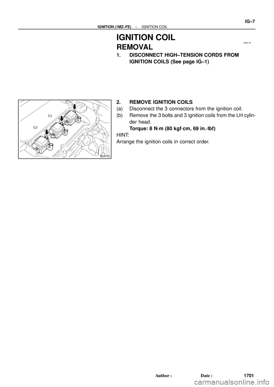
2. REMOVE IGNITION COILS
(a) Disconnect the 3 connectors from the ignition coil.
(b) Remove the 3 bolts and 3 ignition coils from the LH cylin-
der head.
Torque: 8 N´m (80 kgf´cm, 69 in.´lbf)
HINT:
Arrange the ignition coils in correct order.
Page 3666 of 4770
IG02J±01
IG±8
± IGNITION (1MZ±FE)IGNITION COIL
1702 Author�: Date�:
INSTALLATION
Installation is in the reverse order of removal. (See page IG±7)
Page 3667 of 4770
S04589
IG02K±03
± IGNITION (1MZ±FE)CAMSHAFT POSITION SENSOR
IG±9
1703 Author�: Date�:
CAMSHAFT POSITION SENSOR
REMOVAL
REMOVE CAMSHAFT POSITION SENSOR
(a) Disconnect the camshaft position sensor connector.
(b) Remove the 2 bolts and camshaft position sensor.
Torque: 8 N´m (80 kgf´cm, 69 in.´lbf)
Page 3668 of 4770
IG02L±01
IG±10
± IGNITION (1MZ±FE)CAMSHAFT POSITION SENSOR
1704 Author�: Date�:
INSTALLATION
Installation is in the reverse order of removal. (See page IG±9)
Page 3669 of 4770
IG02M±03
P20105
± IGNITION (1MZ±FE)CRANKSHAFT POSITION SENSOR
IG±11
1705 Author�: Date�:
CRANKSHAFT POSITION SENSOR
REMOVAL
1. REMOVE RH FENDER APRON SEAL
2. REMOVE CRANKSHAFT POSITION SENSOR
(a) Remove the bolt and disconnect the crankshaft position
sensor.
Torque: 8 N´m (80 kgf´cm, 69 in.´lbf)
(b) Disconnect the crankshaft position sensor connecter.
Page 3670 of 4770
IG02N±03
P14244
Ohmmeter IG±12
± IGNITION (1MZ±FE)CRANKSHAFT POSITION SENSOR
1706 Author�: Date�:
INSPECTION
NOTICE:
ºColdº and ºHotº in these sentences express the tempera-
ture of the sensor itself. ºColdº is from ±10°C (14°F) to 50°C
(122°F) and ºHotº is from 50°C (122°F) to 100°C (212°F).
INSPECT CRANKSHAFT POSITION SENSOR RESISTANCE
Using an ohmmeter, measure the resistance between termi-
nals.
Resistance:
Cold1,630 ± 2,740 W
Hot2,065 ± 3,225 W
If the resistance is not as specified, replace the crankshaft posi-
tion sensor.
Page 3671 of 4770
IG02O±01
± IGNITION (1MZ±FE)CRANKSHAFT POSITION SENSOR
IG±13
1707 Author�: Date�:
INSTALLATION
Installation is in the reverse order of removal. (See page IG±11)
Page 3681 of 4770
 The")
IN0CQ±03
BO4111
Negative Cable
IN±10
± INTRODUCTIONFOR ALL OF VEHICLES
10 Author�: Date�:
FOR ALL OF VEHICLES
PRECAUTION
1. FOR VEHICLES EQUIPPED WITH SRS AIRBAG AND
SEAT BELT PRETENSIONER
(a) The 1999 CAMRY is equipped with an SRS (Supplemen-
tal Restraint System), such as the driver airbag, front pas-
senger airbag assembly, side airbag assembly and seat
belt pretensioner.
Failure to carry out service operations in the correct se-
quence could cause the supplemental restraint system to
unexpectedly deploy during servicing, possibly leading to
a serious accident.
Further, if a mistake is made in servicing the supplemental
restraint system, it is possible the SRS may fail to operate
when required. Before servicing (including removal or
installation of parts, inspection or replacement), be sure
to read the following items carefully, then follow the cor-
rect procedure described in this manual.
(b) GENERAL NOTICE
(1) Malfunction symptoms of the supplemental re-
straint system are difficult to confirm, so the diag-
nostic trouble codes become the most important
source of information when troubleshooting. When
troubleshooting the supplemental restraint system,
always inspect the diagnostic trouble codes before
disconnecting the battery (See page DI±626).
(2) Work must be started after 90 seconds from the
time the ignition switch is turned to the ºLOCKº posi-
tion and the negative (±) terminal cable is discon-
nected from the battery.
(The supplemental restraint system is equipped
with a back±up power source so that if work is
started within 90 seconds of disconnecting the neg-
ative (±) terminal cable from the battery, the SRS
may deploy.)
When the negative (±) terminal cable is discon-
nected from the battery, memory of the clock and
audio systems will be cancelled. So before starting
work, make a record of the contents memorized by
the each memory system. Then when work is fin-
ished, reset the clock and audio systems as before.
To avoid erasing the memory of each memory sys-
tem, never use a back±up power supply from anoth-
er battery.