Page 3225 of 4770

Start
Unlock all doors manually
Insert key in ignition key cylinder and open driver's doorHINT: Diagnostic mode may be exited
at any time by ungrounding terminal 9
Ground terminal 9 of the wireless door lock ECU and
wait more 1 second.
Remove key from ignition key cylinder and close
driver 's door within 10 seconds.
Press any button on transmitter within 10 seconds.If not performing this operation
within 10 seconds after the
above operation, the mode will
not change into the diagnostic
mode.
If not performing this operation
within 10 seconds after the
above operation, the mode will
not change into the diagnostic
mode.
CONTINUED ON NEXT PAGE
± DIAGNOSTICSWIRELESS DOOR LOCK CONTROL SYSTEM
DI±805
1040 Author�: Date�:
(2) A transmitter recognition code is registered by
pressing any single button of the transmitter to be
registered. Once the code is registered, the ECU
responds again by operating once the lock and un-
lock functions of all the doors.
(3) To register the recognition code of an additional
transmitter, follow the procedure shown in (2).
(4) After completing the registration of the codes, re-
move the test lead from the remote control mirror
switch connector terminals to allow the system to
revert to the normal operation.
(5) Using the registered transmitter, verify that the sys-
tem operates properly.
4. DIAGNOSTIC PROCEDURE
Page 3227 of 4770
DI05O±03
I00217
I00216
I00215
I00241
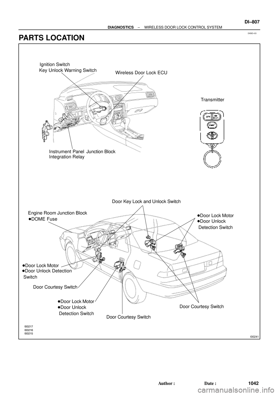
Ignition Switch
Key Unlock Warning Switch
Wireless Door Lock ECU
Transmitter
Instrument Panel Junction Block
Integration Relay
Engine Room Junction Block
�Door Lock Motor
�Door Unlock Detection
Switch
Door Courtesy Switch �DOME FuseDoor Key Lock and Unlock Switch
�Door Lock Motor
�Door Unlock
Detection Switch�Door Lock Motor
�Door Unlock
Detection Switch
Door Courtesy Switch
Door Courtesy Switch
± DIAGNOSTICSWIRELESS DOOR LOCK CONTROL SYSTEM
DI±807
1042 Author�: Date�:
PARTS LOCATION
Page 3228 of 4770
Wiring ColorConditionSTD Voltage")
DI1KR±03
I00227
1 2
63 74
8 5
9 10 11 12 13 14 15
DI±808
± DIAGNOSTICSWIRELESS DOOR LOCK CONTROL SYSTEM
1043 Author�: Date�:
TERMINALS OF ECU
Symbols (Terminals No.)Wiring ColorConditionSTD Voltage (V)
1 ± Ground (GND ± Ground )W ± BAlways.Below 1 V
4 G d(TAIL G d)GRTAIL lamps ºONºBelow 1 V4 ± Ground ( TAIL ± Ground )G ± RTAIL lamps ºOFFº10 ± 14 V
5 G d ( PINI G d )LGAlways.4 ± 6 V5 ± Ground ( PINI ± Ground )LGPush the PANIC switch.Below 1.5 V
7 G d(UL3 G d)RG
Door key lock and unlock switch ºUNLOCKº.
(Driver's Door)Below 1.5 V
7 ± Ground ( UL3 ± Ground )R ± GDoor key lock and unlock switch ºOFFº or ºLOCKº.
(Driver's Door)8 ± 10 V
8 ± 1 (+B ± E )RAlways.10 ± 14 V
9 ± Ground (PRG ± Ground )VIgnition switch ºONº10 ± 14 V
10 ± Ground (KSW ± Ground )L ± B
Key unlock warning switch ºONº.
(Key is inserted into key cylinder)Below 1 V10 Ground (KSW Ground )L B
Key unlock warning switch ºOFFº.10 ± 14 V
11 G d (LSWD G d)LR
Door unlock detection switch ºONº.
(Driver's Door)Below 1 V
11 ± Ground (LSWD ± Ground)L ± RDoor unlock detection switch ºOFFº.
(Driver's Door)10 ± 14 V
12 G d (LSWP G d)Y
Door unlock detection switch ºONº.
(Passenger's Door)Below 1 V
12 ± Ground (LSWP ± Ground)YDoor unlock detection switch ºOFFº.
(Passenger's Door)10 ± 14 V
13 G d(LSWR G d)LY
Door unlock detection switch ºONº.
(Either Rear Door)Below 1 V
13 ± Ground(LSWR ± Ground)L ± YDoor unlock detection switch ºOFFº.
(All Rear Doors)10 ± 14 V
14 G d (CTY G d )RWDoor courtesy switch ºONºBelow 1 V14 ± Ground (CTY ± Ground )R ± WDoor courtesy switch ºOFFº10 ± 14 V
15 G d (L G d )LWDoor key lock and unlock switch ºLOCKºBelow 1 V15 ± Ground (L ± Ground )L ± WDoor key lock and unlock switch ºOFFº or ºUNLOCKº8 ± 10 V
Page 3239 of 4770
I00224
Wireless Door Lock ECU
Key Unlock
Warning
SwitchKSW L±B
W±B
1M1J7 5 5
1
2
3 7
IG10
1D
J/C L±B
W±B1M
Integration Relay
Instrument Panel J/BW6 J10 Instrument Panel J/B
L±B B
J9B
J11
A
± DIAGNOSTICSWIRELESS DOOR LOCK CONTROL SYSTEM
DI±819
1054 Author�: Date�:
Key Unlock Warning Switch Circuit
CIRCUIT DESCRIPTION
When the key is inserted in the ignition key cylinder, the key unlock warning switch comes ON, and when
the key is not inserted the switch is OFF.
When the key unlock warning switch is ON, the ECU operates the key confinement prevention function.
WIRING DIAGRAM
DI05V±03
Page 3243 of 4770
I00301
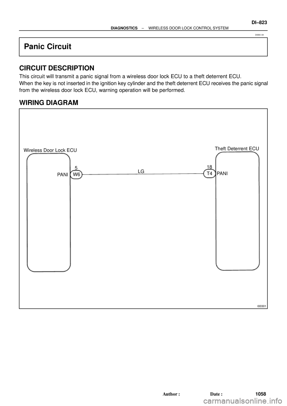
Wireless Door Lock ECUTheft Deterrent ECU
518
LG
PANI
PANIW6T4
± DIAGNOSTICSWIRELESS DOOR LOCK CONTROL SYSTEM
DI±823
1058 Author�: Date�:
Panic Circuit
CIRCUIT DESCRIPTION
This circuit will transmit a panic signal from a wireless door lock ECU to a theft deterrent ECU.
When the key is not inserted in the ignition key cylinder and the theft deterrent ECU receives the panic signal
from the wireless door lock ECU, warning operation will be performed.
WIRING DIAGRAM
DI05X±04
Page 3247 of 4770

DI06N±05
THEFT DETERRENT SYSTEM Check Sheet
Inspector 's name:
Customer 's Name
Date of VehicleRegistration No.
Registration Year
Frame No.
Odometer Reading / /km
Mile
Weather Conditions
When Problem
Occurred Frequency Problem OccursWeather
Outdoor temperature
/ /
� Constant � Sometimes ( Times per day, month)
� Once only Brought in
� Theft deterrent system cannot be set.
� Indicator light does not flash when the theft deterrent system is set.
(It stays on or does not light at all.)
� Theft deterrent system
does not operate.� When unlocked using the
door lock knob.
� When the engine hood is
opened.
� System cannot be
canceled once set.� When door is unlocked using key or wireless door lock control system.
� When the key is inserted in the ignition key cylinder and turned to ACC or ON
position.
(However, only when the system has never operated)
� When the luggage compartment door is opened with the key.
� System cannot be
canceled during warning
operation.� When door is unlocked using key or wireless door lock control system.
� When the key is inserted in the ignition key cylinder and turned to ACC or ON
position.
� Warning operation starts when the system is set and the door or luggage compartment door is opened with
the key.
� Others.
Date Problem First Occurred
� Fine � Cloudy � Rainy � Snowy
� Various/Others
� Hot � Warm � Cool
� Cold (Approx. 5F ( 5C))
Problem Symptom
Malfunction
� Horns only
� Theft deterrent horn only
� Headlights only
� Taillights only
� Starter cut only
� Door lock operation only
± DIAGNOSTICSTHEFT DETERRENT SYSTEM
DI±827
1062 Author�: Date�:
CUSTOMER PROBLEM ANALYSIS CHECK
Page 3248 of 4770

DI1KU±02
DI±828
± DIAGNOSTICSTHEFT DETERRENT SYSTEM
1063 Author�: Date�:
PRE±CHECK
1. Active arming mode:
SETTING THE THEFT DETERRENT MODE
The system will be automatically set to the theft deterrent mode
about 30 seconds after the setting processes listed below are
performed.
Setting Processes: (do processes (1)�(4) in the order)
(1) Remove the ignition key from the key cylinder.
(2) Close all entry points (door, hood and luggage
compartment door).
(3) Use any one of the following methods to lock all the
doors depending on a given condition.
�Use the key to lock the driver or passenger
side door. (as a result, all the doors(including
the engine hood and luggage compartment
door) will be closed and locked), or
�Use the remote control to lock any door (as a
result, all the doors(including the engine
hood and luggage compartment door) will be
closed and locked), or
�If the front right or left door is unlocked when
both the rear doors are already locked, lock
and close the remaining unlocked door by
hand (as a result, all the doors(including the
engine hood and luggage compartment door)
will be closed and locked).
�Close all doors and lock with the engine hood
or luggage compartment door opened, and
close the engine hood or all the doors(includ-
ing the engine hood and luggage compart-
ment door).
(4) About 30 seconds after the above process (3), the
theft deterrent mode will automatically start.
HINT:
The closing/locking of all the entry points (doors, hood and lug-
gage) must remain unchanged for about 30 seconds, the sys-
tem will start the theft deterrent mode.
2. Passive arming mode:
SETTING THE THEFT DETERRENT MODE
The system will be automatically set to the theft deterrent mode
about 30 seconds after the setting processes listed below are
performed.
Setting Processes:
(1) Remove the ignition key from the key cylinder.
(2) Open and close any entry points (door, hood and
luggage compartment door).
Now, all the entry points are closed.
Page 3249 of 4770

I00228
0.25 ± 0.05 sec.
0.25 ± 0.05 sec.
ON
OFF
Horns Sounding and Lights Flashing
Pattern
0.2 ± 0.05 sec.
0.55 ± 0.05 sec. ON
OFF
Output of Key Lock Pattern
± DIAGNOSTICSTHEFT DETERRENT SYSTEM
DI±829
1064 Author�: Date�:
(3) About 30 seconds after the process±(2), on the pre-
vious page the Theft Deterrent mode will automati-
cally start.
HINT:
If, while following above steps, you use the key or the remote
control to lock the door, the system will be set to ACTIVE ARM-
ING MODE.
3. THEFT DETERRENT OPERATION
When the system is set to the theft deterrent mode and any of
the following conditions are met, the system sounds the horns
and flashes the headlights and the taillights for about 1 minute.
At the same time locks all doors (If all doors are not locked at
once, the system repeats door locking operation every 0.55 se-
conds during the one±minute alarm time).
Condition
(1) Any of the doors (Including the engine hood and
luggage compartment door) is unlocked or opened
without the key. *1
(2) The battery terminal is disconnected and recon-
nected. *2
(3) The system receives panic signal from remote key-
less entry. *3
*1: Only active arming mode.
*2: When the ignition key is not inserted in the key
cylinder.