Page 2924 of 4770
 (±)
Engine Room
R/B No. 3
3
45 6 12 (+) (±)
Engine Room
R/B No. 3
3
45 6 12 (+) (±)
Engine Room
R/B No. 3
3
45 612 (+) (±)
Engine Room
R/B No. 3
3
45 6
F07153
3
4
ABS
Actuator
AB")
F00048
12 (+) (±)
Engine Room
R/B No. 3
3
45 6 12 (+) (±)
Engine Room
R/B No. 3
3
45 6 12 (+) (±)
Engine Room
R/B No. 3
3
45 612 (+) (±)
Engine Room
R/B No. 3
3
45 6
F07153
3
4
ABS
Actuator
ABS
Solenoid
Relay
A4
A18
ECUA5
1234
56781
5 2
6 3
7 4
8
SFRH
SFRR
SRLR
SRLH
SFLH
SFLR
SRRH
SRRR
DI±504
± DIAGNOSTICSANTI±LOCK BRAKE SYSTEM (DENSO Made)
739 Author�: Date�:
INSPECTION PROCEDURE
1 Check voltage between terminals 1 and 2 of Engine Room R/B No. 3 (for ABS so-
lenoid relay).
PREPARATION:
Remove ABS solenoid relay from Engine Room R/B No. 3.
CHECK:
Measure the voltage between terminals 1 and 2 of Engine
Room R/B No. 3 (for ABS solenoid relay).
OK:
Voltage: 10 ± 14 V
NG Check and repair harness or connector.
OK
2 Check continuity between terminal 3 of ABS solenoid relay and terminal SRLR,
SRLH, SRRR, SRRH, SFLR, SFLH, SFRR or SFRH of ABS ECU.
CHECK:
Check continuity between terminal 3 of Engine Room R/B No.3
(for ABS solenoid relay) and terminal SRLR, SRLH, SRRR,
SRRH, SFLR, SRLH, SFRR or SFRH of ABS ECU.
OK:
Continuity
HINT:
Resistance of each solenoid coil
SRLR, SRRR, SFLR, SFRR: 4.3 W
SRLH, SRRH, SFLH, SFRH: 8.8 W
NG Repair or replace harness or ABS actuator.
OK
Page 2925 of 4770
F00042
1 2 3
4 5 6
(+)(±)1 2 3
4 5 6
1 2 3
4 5 6 Open
Continuity
Continuity
Continuity
Open
± DIAGNOSTICSANTI±LOCK BRAKE SYSTEM (DENSO Made)
DI±505
740 Author�: Date�:
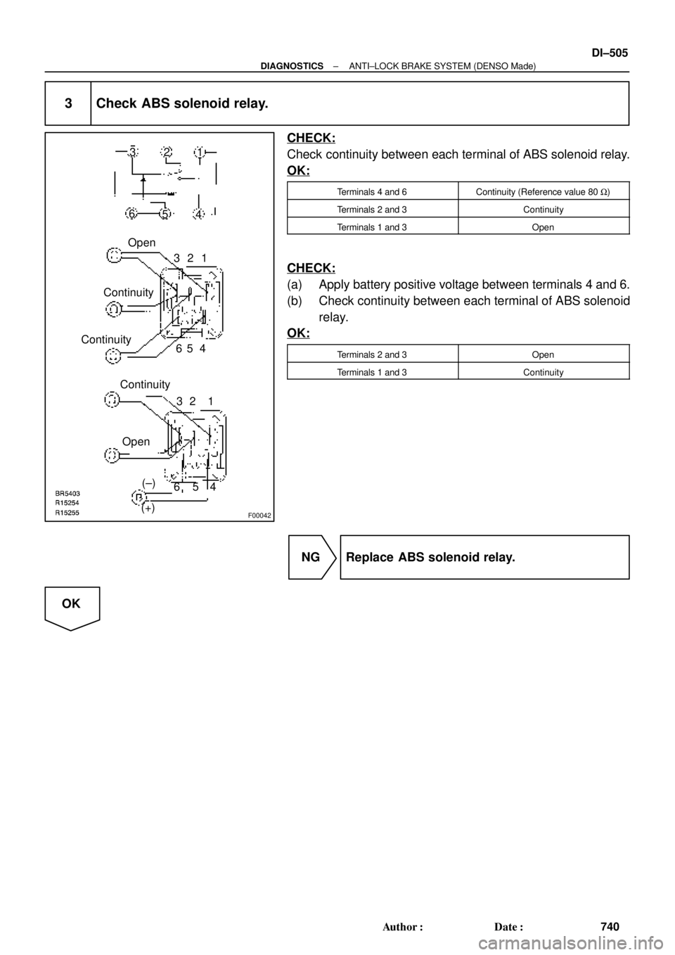
3 Check ABS solenoid relay.
CHECK:
Check continuity between each terminal of ABS solenoid relay.
OK:
Terminals 4 and 6Continuity (Reference value 80 W)
Terminals 2 and 3Continuity
Terminals 1 and 3Open
CHECK:
(a) Apply battery positive voltage between terminals 4 and 6.
(b) Check continuity between each terminal of ABS solenoid
relay.
OK:
Terminals 2 and 3Open
Terminals 1 and 3Continuity
NG Replace ABS solenoid relay.
OK
Page 2926 of 4770
DI±506
± DIAGNOSTICSANTI±LOCK BRAKE SYSTEM (DENSO Made)
741 Author�: Date�:
4 Check for open and short circuit in harness and connector between ABS sole-
noid relay and ABS ECU (See page IN±31).
NG Repair or replace harness or connector.
OK
If the same code is still output after the DTC is deleted, check the contact condition of each con-
nection.
If the connections are normal, the ECU may be defective.
Page 2927 of 4770

DI±507
742 Author�: Date�:
DTC 13, 14 ABS Motor Relay Circuit
CIRCUIT DESCRIPTION
The ABS motor relay supplies power to the ABS pump motor. While th")
± DIAGNOSTICSANTI±LOCK BRAKE SYSTEM (DENSO Made)
DI±507
742 Author�: Date�:
DTC 13, 14 ABS Motor Relay Circuit
CIRCUIT DESCRIPTION
The ABS motor relay supplies power to the ABS pump motor. While the ABS is activated, the ECU switches
the ABS motor relay ON and operates the ABS pump motor.
DTC No.DTC Detecting ConditionTrouble Area
13
Condition 1. or 2. continues for 0.2 sec. or more:
1. ABS ECU terminal IG1 voltage is 9.5 V to 18.5 V, and
when motor relay is ON in the midst of initial check or in
operation of ABS control.*
1
2. Motor relay is ON driving in the midst of initial check or
in operation of ABS control, ABS ECU terminal IG1 volt-
age becomes 9.5 V or less.*
2
�ABS motor relay
�ABS motor relay circuit
�ECU
14
Condition below continues for 4 sec. or more:
When the motor relay is OFF, there is open circuit in MT
terminal of ABS ECU.
*1
Relay contact OFF condition: MT terminal voltage is below 3.6 V.
*
2
Relay contact ON condition: MT terminal voltage is 3.6 V or above.
Fail safe function:
If trouble occurs in the ABS motor relay circuit, the ECU cuts off current to the ABS solenoid relay and prohib-
its ABS control.
DI03I±03
Page 2928 of 4770
F07146
B±G
Fusible
Link
Block
F5 1
F4
1
FL
Main B±G
Battery3
3ABSABS Motor
Relay
2 13
43
3
Engine Room R/B No.3GR±R GR±R1
IK126
A19 R+ABS ECU
GR±L1
A18 MR
W±R2
A4
A41
W±B
EAABS Actuator
3
A4R±W10
A18 MT ALT DI±508
± DIAGNOSTICSANTI±LOCK BRAKE SYSTEM (DENSO Made)
743 Author�: Date�:
WIRING DIAGRAM
Page 2929 of 4770
 (±)
Engine Room
R/B No. 3
2
34 1 (+) (±)
Engine Room
R/B No. 32
34 1 (+) (±)
Engine Room
R/B No. 32
34
1 (+) (±)
Engine Room
R/B No. 3
2
34
F07154
3 3
ECU ECU
ECU
ABS
Motor
Relay2")
F00049
1 (+) (±)
Engine Room
R/B No. 3
2
34 1 (+) (±)
Engine Room
R/B No. 32
34 1 (+) (±)
Engine Room
R/B No. 32
34
1 (+) (±)
Engine Room
R/B No. 3
2
34
F07154
3 3
ECU ECU
ECU
ABS
Motor
Relay2
A4
A4
A18
MT
2
2
ECU
ABS
Actuator
± DIAGNOSTICSANTI±LOCK BRAKE SYSTEM (DENSO Made)
DI±509
744 Author�: Date�:
INSPECTION PROCEDURE
1 Check voltage between terminal 1 of Engine Room R/B No. 3 (for ABS motor
relay) and body ground.
PREPARATION:
Remove ABS motor relay from Engine Room R/B No. 3.
CHECK:
Measure voltage between terminal 1 of Engine Room R/B No.
3 (for ABS motor relay) and body ground.
OK:
Voltage: 10 ± 14 V
NG Check and repair harness or connector.
OK
2 Check continuity between terminal 2 of ABS motor relay and terminal MT of ABS
ECU.
CHECK:
Check continuity between terminal 2 of Engine Room R/B No.3
(for ABS motor relay) and terminal MT of ABS ECU.
OK:
Continuity
HINT:
There is a resistance of 4 ~ 6 W between terminals A4 ± 2 and
A4 ± 3 of ABS actuator.
NG Repair or replace harness or ABS actuator.
OK
Page 2930 of 4770
F00044
1 2
3 4
1 2
3 4
1 2
3 4 Open
Continuity
Continuity
(+)(±)
DI±510
± DIAGNOSTICSANTI±LOCK BRAKE SYSTEM (DENSO Made)
745 Author�: Date�:
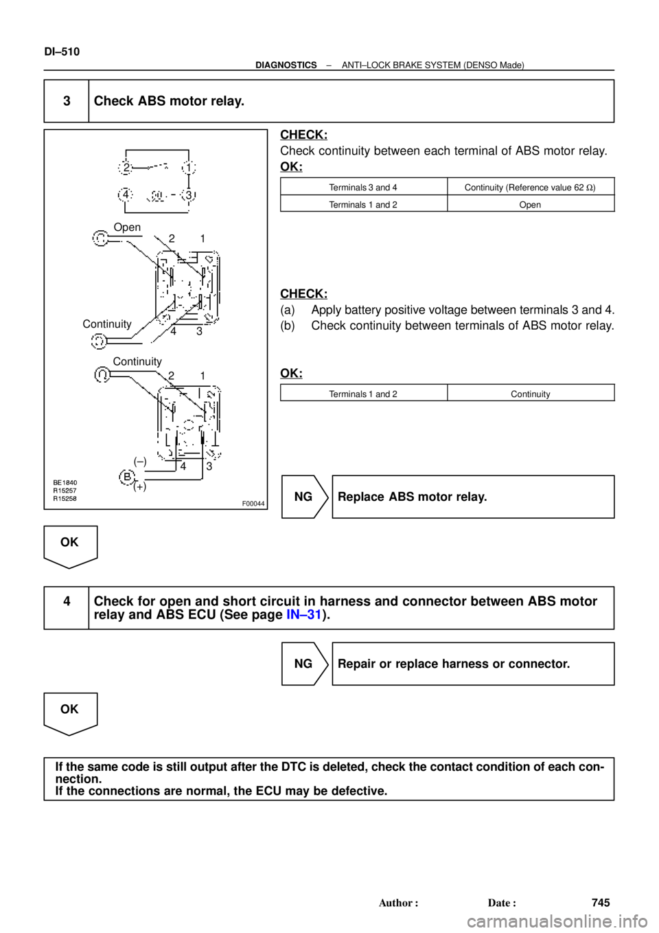
3 Check ABS motor relay.
CHECK:
Check continuity between each terminal of ABS motor relay.
OK:
Terminals 3 and 4Continuity (Reference value 62 W)
Terminals 1 and 2Open
CHECK:
(a) Apply battery positive voltage between terminals 3 and 4.
(b) Check continuity between terminals of ABS motor relay.
OK:
Terminals 1 and 2Continuity
NG Replace ABS motor relay.
OK
4 Check for open and short circuit in harness and connector between ABS motor
relay and ABS ECU (See page IN±31).
NG Repair or replace harness or connector.
OK
If the same code is still output after the DTC is deleted, check the contact condition of each con-
nection.
If the connections are normal, the ECU may be defective.
Page 2931 of 4770

DI±511
746 Author�: Date�:
DTC 21, 22, 23, 24 ABS Actuator Solenoid Circuit
CIRCUIT DESCRIPTION
This solenoid goes on when signals are received from")
± DIAGNOSTICSANTI±LOCK BRAKE SYSTEM (DENSO Made)
DI±511
746 Author�: Date�:
DTC 21, 22, 23, 24 ABS Actuator Solenoid Circuit
CIRCUIT DESCRIPTION
This solenoid goes on when signals are received from the ECU and controls the pressure acting on the wheel
cylinders thus controlling the braking force.
DTC No.DTC Detecting ConditionTrouble Area
21
Condition 1. or 2. continues for 0.05 sec. or more:
1. IG1 terminal voltage of ABS ECU is 9.5 ± 18.5 V, there
is open or short circuit in actuator solenoid SFRR or
SFRH.
2. IG1 terminal voltage of ABS ECU is 9.5 ± 18.5 V, and
while ABS is control in operation.*
1
�ABS actuator
�SFRR or SFRH circuit
22
Condition 1. or 2. continues for 0.05 sec. or more:
1. IG1 terminal voltage of ABS ECU is 9.5 ± 18.5 V, there
is open or short circuit in actuator solenoid SFLR or
SFLH.
2. IG1 terminal voltage of ABS ECU is 9.5 ± 18.5 V, and
while ABS is control in operation.*
1
�ABS actuator
�SFLR or SFLH circuit
23
Condition 1. or 2. continues for 0.05 sec. or more:
1. IG1 terminal voltage of ABS ECU is 9.5 ± 18.5 V, there
is open or short circuit in actuator solenoid SRRR or
SRRH.
2. IG1 terminal voltage of ABS ECU is 9.5 ± 18.5 V, and
while ABS is control in operation.*
1
�ABS actuator
�SRRR or SRRH circuit
24
Condition 1. or 2. continues for 0.05 sec. or more:
1. IG1 terminal voltage of ABS ECU is 9.5 ± 18.5 V, there
is open or short circuit in actuator solenoid SRLR or
SRLH.
2. IG1 terminal voltage of ABS ECU is 9.5 ± 18.5 V, and
while ABS is control in operation.*
1
�ABS actuator
�SRLR or SRLH circuit
*1
Solenoid relay contact ON condition:
All of solenoid terminal voltage is half of IG1 terminal voltage or less than.
Fail safe function:
If trouble occurs in the actuator solenoid circuit, the ECU cuts off current to the ABS solenoid relay and pro-
hibits ABS control.
DI03J±03