Page 4106 of 4770
FUEL PUMP
1505 Author�: Date�:
FUEL PUMP
ON±VEHICLE INSPECTION
1. CHECK FUEL PUMP OPERATION
(a) Connect")
S05358
TOYOTA
Hand Held TesterSF079±04
S05353
S05359
Fuel Tube Connector
SF±6
± SFI (1MZ±FE)FUEL PUMP
1505 Author�: Date�:
FUEL PUMP
ON±VEHICLE INSPECTION
1. CHECK FUEL PUMP OPERATION
(a) Connect a TOYOTA hand±held tester to the DLC3.
(b) Turn the ignition switch ON and push the TOYOTA hand±
held tester main switch ON.
NOTICE:
Do not start the engine.
(c) Select the ACTIVE TEST mode on the TOYOTA hand±
held tester.
(d) Please refer to the TOYOTA hand±held tester operator's
manual for further details.
(e) If you have no TOYOTA hand±held tester, connect the
positive (+) and negative (±) leads from the battery to the
fuel pump connector. (See step 7)
(f) Check that there is pressure in the fuel inlet hose from the
fuel filter.
HINT:
If there is fuel pressure, you will hear the sound of fuel flowing.
If there is no pressure, check these parts:
Fusible link
Fuses
EFI main relay
Fuel pump
ECM
Wiring connections
(g) Turn the ignition switch OFF.
(h) Disconnect the TOYOTA hand±held tester from the
DLC3.
2. CHECK FUEL PRESSURE
(a) Check the battery positive voltage is above 12 V.
(b) Disconnect the negative (±) terminal cable from the bat-
tery.
(c) Purchase the new No.1 fuel pipe and take out the fuel
tube connector from its pipe.
Part No. 23801±20041
Page 4153 of 4770
S05392
EFI Main
Relay
SF088±03
S04970
Ohmmeter OhmmeterContinuity
No Continuity 12
5
3
S04969
Ohmmeter
Continuity 12
5
3
Battery
± SFI (1MZ±FE)EFI MAIN RELAY
SF±53
1552 Author�: Date�:
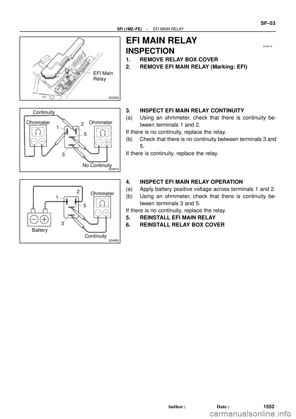
EFI MAIN RELAY
INSPECTION
1. REMOVE RELAY BOX COVER
2. REMOVE EFI MAIN RELAY (Marking: EFI)
3. INSPECT EFI MAIN RELAY CONTINUITY
(a) Using an ohmmeter, check that there is continuity be-
tween terminals 1 and 2.
If there is no continuity, replace the relay.
(b) Check that there is no continuity between terminals 3 and
5.
If there is continuity, replace the relay.
4. INSPECT EFI MAIN RELAY OPERATION
(a) Apply battery positive voltage across terminals 1 and 2.
(b) Using an ohmmeter, check that there is continuity be-
tween terminals 3 and 5.
If there is no continuity, replace the relay.
5. REINSTALL EFI MAIN RELAY
6. REINSTALL RELAY BOX COVER
Page 4154 of 4770
S05389
Circuit Opening
RelaySF089±03
S04970
Ohmmeter OhmmeterContinuity
No Continuity 12
5
3
S04969
Ohmmeter
Continuity 12
5
3
Battery SF±54
± SFI (1MZ±FE)CIRCUIT OPENING RELAY
1553 Author�: Date�:
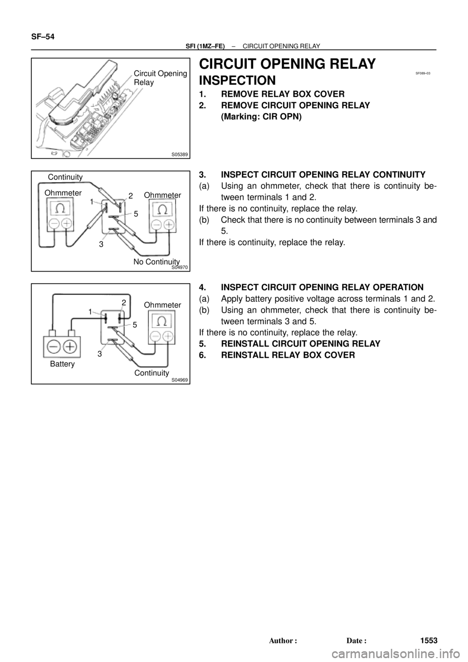
CIRCUIT OPENING RELAY
INSPECTION
1. REMOVE RELAY BOX COVER
2. REMOVE CIRCUIT OPENING RELAY
(Marking: CIR OPN)
3. INSPECT CIRCUIT OPENING RELAY CONTINUITY
(a) Using an ohmmeter, check that there is continuity be-
tween terminals 1 and 2.
If there is no continuity, replace the relay.
(b) Check that there is no continuity between terminals 3 and
5.
If there is continuity, replace the relay.
4. INSPECT CIRCUIT OPENING RELAY OPERATION
(a) Apply battery positive voltage across terminals 1 and 2.
(b) Using an ohmmeter, check that there is continuity be-
tween terminals 3 and 5.
If there is no continuity, replace the relay.
5. REINSTALL CIRCUIT OPENING RELAY
6. REINSTALL RELAY BOX COVER
Page 4270 of 4770
B00796
Starter
Relay
ST03Q±01
P07170
Ohmmeter
Ohmmeter No
ContinuityContinuity 1
3
25
P07171
Ohmmeter
Continuity1
3
25
Battery ST±20
± STARTING (5S±FE)STARTER RELAY
1727 Author�: Date�:
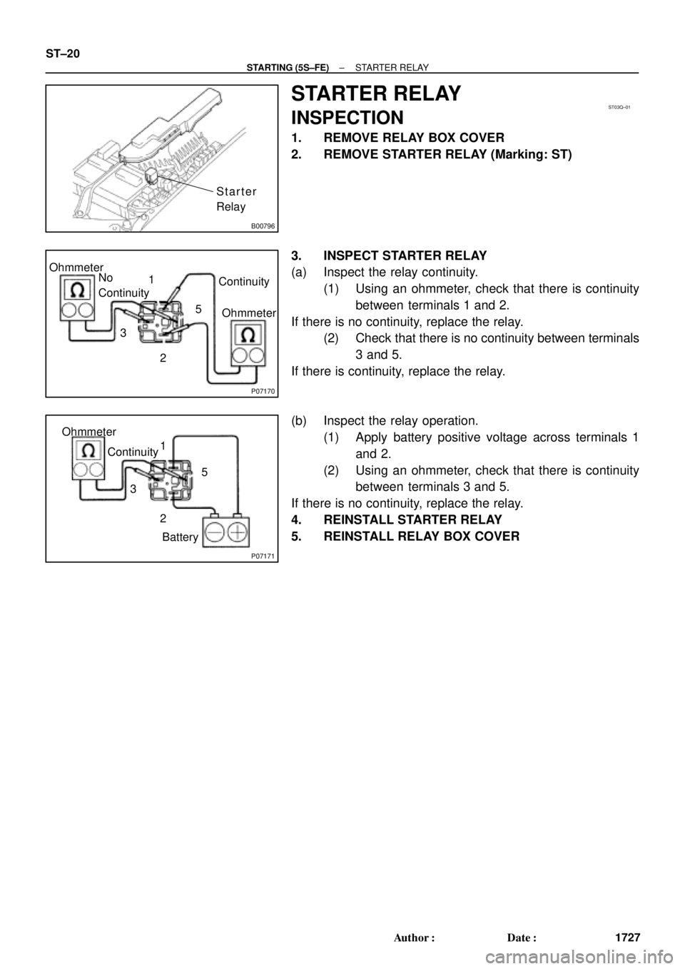
STARTER RELAY
INSPECTION
1. REMOVE RELAY BOX COVER
2. REMOVE STARTER RELAY (Marking: ST)
3. INSPECT STARTER RELAY
(a) Inspect the relay continuity.
(1) Using an ohmmeter, check that there is continuity
between terminals 1 and 2.
If there is no continuity, replace the relay.
(2) Check that there is no continuity between terminals
3 and 5.
If there is continuity, replace the relay.
(b) Inspect the relay operation.
(1) Apply battery positive voltage across terminals 1
and 2.
(2) Using an ohmmeter, check that there is continuity
between terminals 3 and 5.
If there is no continuity, replace the relay.
4. REINSTALL STARTER RELAY
5. REINSTALL RELAY BOX COVER
Page 4290 of 4770
B00796
Starter
Relay
ST022±01
P07170
Ohmmeter
Ohmmeter No
ContinuityContinuity 1
3
25
P07171
Ohmmeter
Continuity1
3
25
Battery ST±20
± STARTING (1MZ±FE)STARTER RELAY
1747 Author�: Date�:
STARTER RELAY
INSPECTION
1. REMOVE RELAY BOX COVER
2. REMOVE STARTER RELAY (Marking: ST)
3. INSPECT STARTER RELAY
(a) Inspect the relay continuity.
(1) Using an ohmmeter, check that there is continuity
between terminals 1 and 2.
If there is no continuity, replace the relay.
(2) Check that there is no continuity between terminals
3 and 5.
If there is continuity, replace the relay.
(b) Inspect the relay operation.
(1) Apply battery positive voltage across terminals 1
and 2.
(2) Using an ohmmeter, check that there is continuity
between terminals 3 and 5.
If there is no continuity, replace the relay.
4. REINSTALL STARTER RELAY
5. REINSTALL RELAY BOX COVER
Page 4605 of 4770

Toyota Supports ASE CertificationPage 1 of 3
EL011±00Title:
DAYTIME RUNNING LIGHT DISABLING
PROCEDURE
Models:
All Models
Technical Service
BULLETIN
October 6, 2000
Some customers may request to have the Daytime Running Lights (DRL) on their Toyota
vehicle disabled. These customers may live or work in military bases or in communities
that have light±sensitive gates or guardhouses. This bulletin provides instructions for
disabling the feature on the Toyota vehicles listed below. If the Daytime Running Lights
(DRL) have been previously disabled, the information in this bulletin can be used to
enable the feature at the request of the customer.
IMPORTANT:
Please be sure the customer is informed that when the Daytime Running Lights (DRL)
are being disabled, although it is not required by the Federal Motor Vehicle Safety
Standards for safety compliance, it has been listed as a safety feature in advertising
brochures. In addition, on models equipped with the Twilight Sentinel feature, the
headlights will be defaulted to a manual system and will no longer function
automatically.
�All Models equipped with Daytime Running Lights (DRL) (see chart below).
TOOLS & MATERIALSQUANTITY
Wire Harness Repair Kit1
NOTE:
After referencing the chart, proceed to the repair procedure on the following pages.
MODELMODEL YEARECUCONNECTORPIN#EWD PG#
Avalon1999DRL Main RelayD41110Avalon2000Body ECUB5699
Camry S/D*199923102Camry S/D*2000DRL Main RelayD61096
Camry Solara*1999/2000
DRL Main RelayD6
23102/96
Celica*2000Body ECUB61775
Corolla*1999/2000D32384/72
ECHO2000D21267
4Runner2000D8299
Land Cruiser1999/2000D8290/88
MR2 Spyder2000DRL Main RelayD21269
RAV41999/2000
DRL Main Relay
D1772/70
Sienna1999/2000D4283/81
Tacoma2000D82115
Tundra2000D795
* Vehicles equipped with Twilight Sentinel.
OP CODEDESCRIPTIONTIMEOPNT1T2
N/ANot Applicable to Warranty ±±±±
ELECTRICAL
Introduction
Applicable
Vehicles
Parts
Information
Reference
Chart
Warranty
Information
Page 4606 of 4770

DAYTIME RUNNING LIGHT DISABLING PROCEDURE ± EL011±00 October 6, 2000
Page 2 of 3
1. Disconnect the Battery.
2. Use the locking pick tool from the wire
harness repair kit and back out the
terminal from the appropriate
connector for the DRL Relay or Body
ECU. See the Reference Chart on
Page 1 of this bulletin for pin and
connector information.
3. Insulate the removed terminal using
vinyl electrical tape.
4. Secure the wire and terminal to the
outside of the wire harness using vinyl
electrical tape.
NOTE:
For the 2000 MY Avalon, proceed to
Step 5. For all remaining models,
proceed to Step 6.
5. For 2000 model year Avalon:
A. Order a new terminal with lead that
is the same size and type as the
terminal previously removed from
the connector. (PN 82998±12690)
B. Securely attach a 45 cm/ 18 in wire
with an outside diameter of 2.0 mm
or larger to the tail of the new
terminal.
Repair
ProcedureDRL Relay or Body ECU
W/H
Insulate
Terminal
Tape insulated
terminal to
outside of
wire harness.
P.N. 82998±12690