Page 3269 of 4770

I00266
Theft Deterrent ECU
TAIL
T3
11
G±R
B BJ/C J33
G±R
10
IG1
G±RA
AJ2
J/C
G±R 1C
6
2
3
Taillight Control Relay
1
5
TAIL81S
1C
9
1B
4 Instrument Panel J/B
B±R
Light
Failure
Sensor
Turn & Clearance
Light
1F9
F4
1
FL
BLOCK
FL MAIN
Battery
B±G ALT
± DIAGNOSTICSTHEFT DETERRENT SYSTEM
DI±849
1084 Author�: Date�:
Taillight Control Relay Circuit
CIRCUIT DESCRIPTION
When the theft deterrent system is activated, it causes the Tr in the ECU to switch ON and OFF at approxi-
mately 0.4 sec. intervals. This switches the taillight control relay ON and OFF, thus flashing the taillights (See
the wiring diagram below).
In this condition, if any of the following operations is done, the Tr in the ECU goes OFF and the taillight control
relay switches OFF, thus stopping the taillights flashing:
(1) Unlock the front LH or RH door with key.
(2) Turn the ignition switch to ACC or ON position.
(3) Unlock the doors with the wireless door lock control system.
(4) Wait for approximately 60 seconds.
(5) Push the panic switch of the wireless door lock control system.
WIRING DIAGRAM
DI06Y±06
Page 3270 of 4770
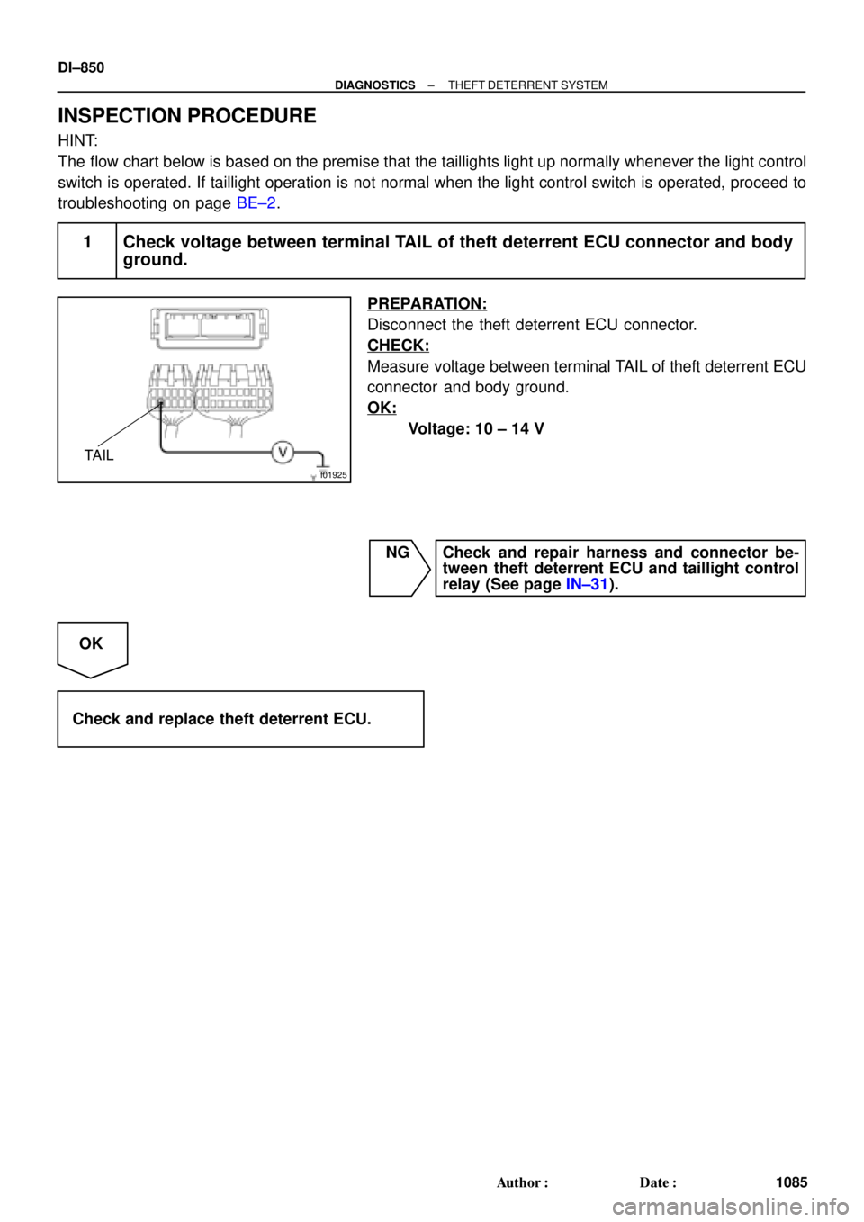
I01925
TAIL
DI±850
± DIAGNOSTICSTHEFT DETERRENT SYSTEM
1085 Author�: Date�:
INSPECTION PROCEDURE
HINT:
The flow chart below is based on the premise that the taillights light up normally whenever the light control
switch is operated. If taillight operation is not normal when the light control switch is operated, proceed to
troubleshooting on page BE±2.
1 Check voltage between terminal TAIL of theft deterrent ECU connector and body
ground.
PREPARATION:
Disconnect the theft deterrent ECU connector.
CHECK:
Measure voltage between terminal TAIL of theft deterrent ECU
connector and body ground.
OK:
Voltage: 10 ± 14 V
NG Check and repair harness and connector be-
tween theft deterrent ECU and taillight control
relay (See page IN±31).
OK
Check and replace theft deterrent ECU.
Page 3284 of 4770
I04444
Theft Deterrent ECU
DSWD
CTY
DSWP
4
T4
T4
T41
5 R±G A
J10 C
R±G 1
1G 7
1S
Integration
Relay
4
1G R±G
Door Courtesy
Switch Front LH
1
R±W J/C
E
J34 D
J33
D
J33
D J33 6
4
12
1S R±B
1 Door Courtesy
Switch Rear LH
J9
R±W
R±W 8
IN2 R±W
1 Door Courtesy
Switch Rear RH
R±W
1
Diode
2
R±G J/C
E
J33
J34D
E
J33R±G R±G
IN26
R±G
1 Door Courtesy
Switch Front RH
J/C
Instrument panel J/B DI±864
± DIAGNOSTICSTHEFT DETERRENT SYSTEM
1099 Author�: Date�:
Door Courtesy Switch Circuit
CIRCUIT DESCRIPTION
The door courtesy switch goes ON when the door is opened and goes OFF when the door is closed.
WIRING DIAGRAM
DI075±06
Page 3640 of 4770
BE0A4±04
I21685
E/G Room J/B No.2
� HEAD LH Fuse
(w/o Daytime Running Light)
� HEAD RH Fuse
(w/o Daytime Running Light)
� HEAD LH (UPR) Fuse
(w/ Daytime Running Light)
� HEAD RH (UPR) Fuse
(w/ Daytime Running Light)
� DOME Fuse
� ECU±B Fuse
� Headlight Control Relay
E/G Room R/B No.2
(w/ Daytime Running Light)
� HEAD LH (LWR) Fuse
� HEAD RH (LWR) Fuse
� DRL No.2 Fuse
� Daytime Running Light Relay No.2
� Daytime Running Light Relay No.3
� Daytime Running Light Relay No.4
Headlight
Instrument Panel J/B No.1
� GAUGE Fuse
� TAIL Fuse
� Taillight Control Relay
� Integration Relay
Daytime Running
Light Relay (Main)Ignition Switch
Combination Switch
� Light Control Switch
� Headlight Dimmer Switch
Door Courtesy Switch
Light Failure Sensor
Taillight
Automatic Light
Control Sensor
BE±22
± BODY ELECTRICALHEADLIGHT AND TAILLIGHT SYSTEM
2232 Author�: Date�:
2001 CAMRY (RM819U)
HEADLIGHT AND TAILLIGHT SYSTEM
LOCATION
Page 3642 of 4770

N20149
HEADHi beam
TAIL
OFF
Flash
87
17 1614
13
BE10D±02
Z08521
1
2
341 2
43
N14863
12
35
12 35
I21684
Wire Harness Side
3 2 1745 98
116
1015 12 1413 16 17 18 BE±24
± BODY ELECTRICALHEADLIGHT AND TAILLIGHT SYSTEM
2234 Author�: Date�:
2001 CAMRY (RM819U)
INSPECTION
1. INSPECT LIGHT CONTROL SWITCH CONTINUITY
Switch positionTester connectionSpecified condition
OFF±No continuity
TAIL14 ± 16Continuity
HEAD13 ± 14 ± 16Continuity
If continuity is not as specified, replace the switch.
2. INSPECT HEADLIGHT DIMMER SWITCH CONTINU-
ITY
Switch positionTester connectionSpecified condition
Low beam16 ± 17Continuity
High beam7 ± 16Continuity
Flash7 ± 8 ± 16Continuity
If continuity is not as specified, replace the switch.
3. INSPECT HEADLIGHT RELAY CONTINUITY
ConditionTester connectionSpecified condition
Constant1 ± 2Continuity
Apply B+ between
terminals 1 and 2.3 ± 4Continuity
If continuity is not as specified, replace the relay.
4. INSPECT TAILLIGHT CONTROL RELAY CONTINUITY
ConditionTester connectionSpecified condition
Constant1 ± 2Continuity
Apply B+ between
terminals 1 and 2.3 ± 5Continuity
If continuity is not as specified, replace the relay.
5. w/ Daytime running light system:
INSPECT DAYTIME RUNNING LIGHT RELAY (MAIN)
CIRCUIT
Disconnect the connector from the relay and inspect the con-
nector on the wire harness side.
Page 3643 of 4770
Tester connection
ConditionSpecified condition
1 ± Grou")
Z08523
1
2
341 2
43
I21683
12
34
1
2 4
3
55
± BODY ELECTRICALHEADLIGHT AND TAILLIGHT SYSTEM
BE±25
2235 Author�: Date�:
2001 CAMRY (RM819U)Tester connection
ConditionSpecified condition
1 ± GroundConstantBattery positive voltage
2 ± GroundConstantBattery positive voltage
3 ± GroundConstantBattery positive voltage
4 ± GroundLight control switch position OFF or HEADNo voltage
4 ± GroundLight control switch position TAILContinuity
5 ± GroundConstantBattery positive voltage
7 ± GroundLight control switch position OFF or TAILNo continuity
7 ± GroundLight control switch position HEADContinuity
8 ± GroundHeadlight dimmer switch position
Low beamNo continuity
8 ± GroundHeadlight dimmer switch position
High beam of FlashContinuity
9 ± GroundEngine StopNo voltage
9 ± GroundEngine RunningBattery positive voltage
10 ± GroundIgnition switch position LOCK or ACCNo voltage
10 ± GroundIgnition switch position ON or STARTBattery positive voltage
14 ± GroundConstantContinuity
17 ± GroundBrake fluid level warning position OFFNo continuity
17 ± GroundBrake fluid level warning position ONContinuity
18 ± GroundParking brake switch position OFF
(Parking brake lever released)No continuity
18 ± GroundParking brake switch position ON
(Parking brake lever pulled up)Continuity
If circuit is as specified, try replacing the relay with a new one.
If circuit is not as specified, inspect the circuits connected to oth-
er parts.
6. w/ Daytime running light system:
INSPECT DAYTIME RUNNING LIGHT NO.2 RELAY
CONTINUITY
ConditionTester connectionSpecified condition
Constant1 ± 4, 2 ± 4Continuity
Apply B+ between
terminals 2 and 4.3 ± 4Continuity
If continuity is not as specified, replace the relay.
7. w/ Daytime running light system:
INSPECT DAYTIME RUNNING LIGHT NO.3 RELAY-
CONTINUITY
ConditionTester connectionSpecified condition
Constant1 ± 2, 3 ± 4Continuity
Apply B+ between
terminals 1 and 2.3 ± 5Continuity
If continuity is not as specified, replace the relay.
Page 3644 of 4770

8. w/ Daytime running light system:
INSPECT DAYTIME RUNNING LIGHT")
Z08559
1
2
341 2
43
I08422
I08423
BE±26
± BODY ELECTRICALHEADLIGHT AND TAILLIGHT SYSTEM
2236 Author�: Date�:
2001 CAMRY (RM819U)
8. w/ Daytime running light system:
INSPECT DAYTIME RUNNING LIGHT NO.4 RELAY
CONTINUITY
ConditionTester connectionSpecified condition
Constant3 ± 4Continuity
Apply B+ between
terminals 3 and 4.1 ± 2Continuity
If continuity is not as specified, replace the relay.
9. INSPECT LIGHT AUTO TURN OFF SYSTEM
(See Integration relay circuit on page BE±14)
10. w/ Automatic Light Control System:
INSPECT AUTOMATIC LIGHT CONTROL
(a) Turn the ignition switch ON.
(b) Turn the light control switch to OFF.
(c) Parking brake lever released.
(d) Gradually cover the top of the sensor.
(e) Verify that the lights should turn ON the accessory lights
and the headlights.
11. w/ Automatic Light Control System:
INSPECT AUTOMATIC LIGHT CONTROL
(a) Gradually expose the sensor.
(b) Verify that the lights should turn OFF the headlights and
the accessory lights.
12. w/ Automatic Light Control System:
INSPECT LIGHT±OFF CONDITION
(a) Turn the ignition switch ON.
(b) Gradually cover the top of the sensor.
Lights auto ON:
13. w/ Automatic Light Control System:
INSPECT LIGHTS±ON CONDITION
(a) Open the driver's door while the ignition switch is OFF.
(b) Turn the light control switch to OFF leaving the door open
and cover the top of the sensor, and verify that the lights
go on when the ignition switch is turned ON.
Page 3677 of 4770
 Care must be taken when jacking up and supporting the
vehicle. Be sure to lift and support the")
IN0253
WRONG CORRECT
IN0252
WRONG CORRECT IN±6
± INTRODUCTIONREPAIR INSTRUCTIONS
6 Author�: Date�:
(k) Care must be taken when jacking up and supporting the
vehicle. Be sure to lift and support the vehicle at the prop-
er locations (See page IN±8).
�Cancel the parking brake on the level place and
shift the transmission in Neutral (or N position).
�When jacking up the front wheels of the vehicle at
first place stoppers behind the rear wheels.
�When jacking up the rear wheels of the vehicle at
first place stoppers before the front wheels.
�When either the front or rear wheels only should be
jacked up, set rigid racks and place stoppers in front
and behind the other wheels on the ground.
�After the vehicle is jacked up, be sure to support it
on rigid racks . It is extremely dangerous to do any
work on a vehicle raised on a jack alone, even for
a small job that can be finished quickly.
(l) Observe the following precautions to avoid damage to the
following parts:
(1) Do not open the cover or case of the ECU unless
absolutely necessary. (If the IC terminals are
touched, the IC may be destroyed by static electric-
ity.)
(2) To disconnect vacuum hoses, pull off the end, not
the middle of the hose.
(3) To pull apart electrical connectors, pull on the con-
nector itself, not the wires.
(4) Be careful not to drop electrical components, such
as sensors or relays. If they are dropped on a hard
floor, they should be replaced and not reused.
(5) When steam cleaning an engine, protect the elec-
tronic components, air filter and emission±related
components from water.
(6) Never use an impact wrench to remove or install
temperature switches or temperature sensors.
(7) When checking continuity at the wire connector, in-
sert the tester probe carefully to prevent terminals
from bending.
(8) When using a vacuum gauge, never force the hose
onto a connector that is too large. Use a step±down
adapter for adjustment. Once the hose has been
stretched, it may leak air.