Page 3030 of 4770
DI±610
± DIAGNOSTICSABS & TRACTION CONTROL SYSTEM
845 Author�: Date�:
DTC Always ON ABS & TRAC ECU Malfunction
CIRCUIT DESCRIPTION
DTC No.DTC Detecting ConditionTrouble Area
Always ONABS & TRAC ECU internal malfunction is detected.�ECU
Fail safe function:
If any trouble occurs in the power source circuit, the ECU cuts off current to the ABS & TRAC solenoid relay
and prohibits ABS control and TRAC control.
INSPECTION PROCEDURE
1 Is DTC output?
Check DTC on page DI±574.
YES Repair circuit indicated by the code output.
NO
2 Is normal code displayed?
YES Check solenoid relay. Check for short circuit in
harness and connector between solenoid relay
and DLC1 (See page IN±31).
NO
3 Does ABS warning light go off?
YES Check for open and short circuit in harness and
connector between ECU±IG fuse and ABS &
TRAC ECU (See page IN±31).
NO
DI1JQ±03
Page 3032 of 4770

F00168
BatteryABS & TRAC
Solenoid Relay Engine Room R/B No. 3
3ABS & TRAC
ECU
A8 1
R±L
C 5 4
IG3 IK2 6
J/C C10
EA4ABS Warning Light 8
12 II3
G±B23 2
22 ABS & TRAC
Actuator
DLC1 Short
Pin
WA
J29 33 3 3
3
W±B4
ABS & TRAC
ECUR±L
4
R±L
II3 5
G±B
C C G±B R±LC107
ABS & TRAC ECU R±LR±L
J/C
D 1D
GAUGE Instrument Panel J/B
A16 J4 D
G±B4 W±L
2
DI±612
± DIAGNOSTICSABS & TRACTION CONTROL SYSTEM
847 Author�: Date�:
ABS Warning Light Circuit
CIRCUIT DESCRIPTION
If the ECU detects a trouble, it lights the ABS warning light while at the same time prohibiting ABS control.
At this time, the ECU records a DTC in memory.
Connect terminals Tc and E
1 of the DLC1 or DLC2 to make the ABS warning light blink and output the DTC.
WIRING DIAGRAM
INSPECTION PROCEDURE
Troubleshoot in accordance with the chart below for each trouble symptom.
ABS warning light does not light upGo to step 1
ABS warning light remains onGo to step 3
1 Check ABS warning light.
See combination meter troubleshooting on page BE±2.
NG Repair bulb or combination meter assembly.
OK
DI04V±04
Page 3033 of 4770
 (±)
(+) (±)1 2 3
4 5 6 Continuity
± DIAGNOSTICSABS & TRACTION CONTROL SYSTEM
DI±613
848 Author�: Date�:
2 C")
F00043
1 2 3
4 5 6
1 2 3
4 5 6
1 2 3
4 65 Open
Continuity
Continuity
Open Continuity
(+) (±)
(+) (±)1 2 3
4 5 6 Continuity
± DIAGNOSTICSABS & TRACTION CONTROL SYSTEM
DI±613
848 Author�: Date�:
2 Check ABS & TRAC solenoid relay.
PREPARATION:
Remove ABS & TRAC solenoid relay from Engine Room R/B
No. 3.
CHECK:
Check continuity between each terminal of ABS & TRAC sole-
noid relay.
OK:
Terminals 4 and 6Continuity (Reference value 80 W)
Terminals 2 and 3Continuity
Terminals 1 and 3Open
CHECK:
(a) Apply battery positive voltage between terminals 4 and 6.
(b) Check continuity between each terminal of ABS & TRAC
solenoid relay.
OK:
Terminals 2 and 3Open
Terminals 1 and 3Continuity
CHECK:
Connect the � test lead to terminal 5 and the � lead to terminal
3. Check continuity between the terminals.
OK:
Continuity
If there is no continuity, connect the � test lead to terminal 5
and the � lead to terminal 3. Recheck continuity between ter-
minals.
NG Replace ABS & TRAC solenoid relay.
OK
Check for open circuit in harness and connector between DLC1, ABS & TRAC solenoid relay and
body ground (See page IN±31).
Page 3034 of 4770
DI±614
± DIAGNOSTICSABS & TRACTION CONTROL SYSTEM
849 Author�: Date�:
3 Is DTC output?
Check DTC on page DI±574.
YES Repair circuit indicated by the code output.
NO
4 Does ABS warning light go off?
NO Check for short circuit in harness and connec-
tor between ABS warning light, DLC1 and ABS
& TRAC ECU (See page IN±31).
YES
5 Check ABS & TRAC solenoid relay (See step 2).
NG Replace ABS & TRAC solenoid relay.
OK
Check for short circuit in harness and connector between DLC1 and ABS & TRAC solenoid relay
(See page IN±31).
Page 3227 of 4770
DI05O±03
I00217
I00216
I00215
I00241
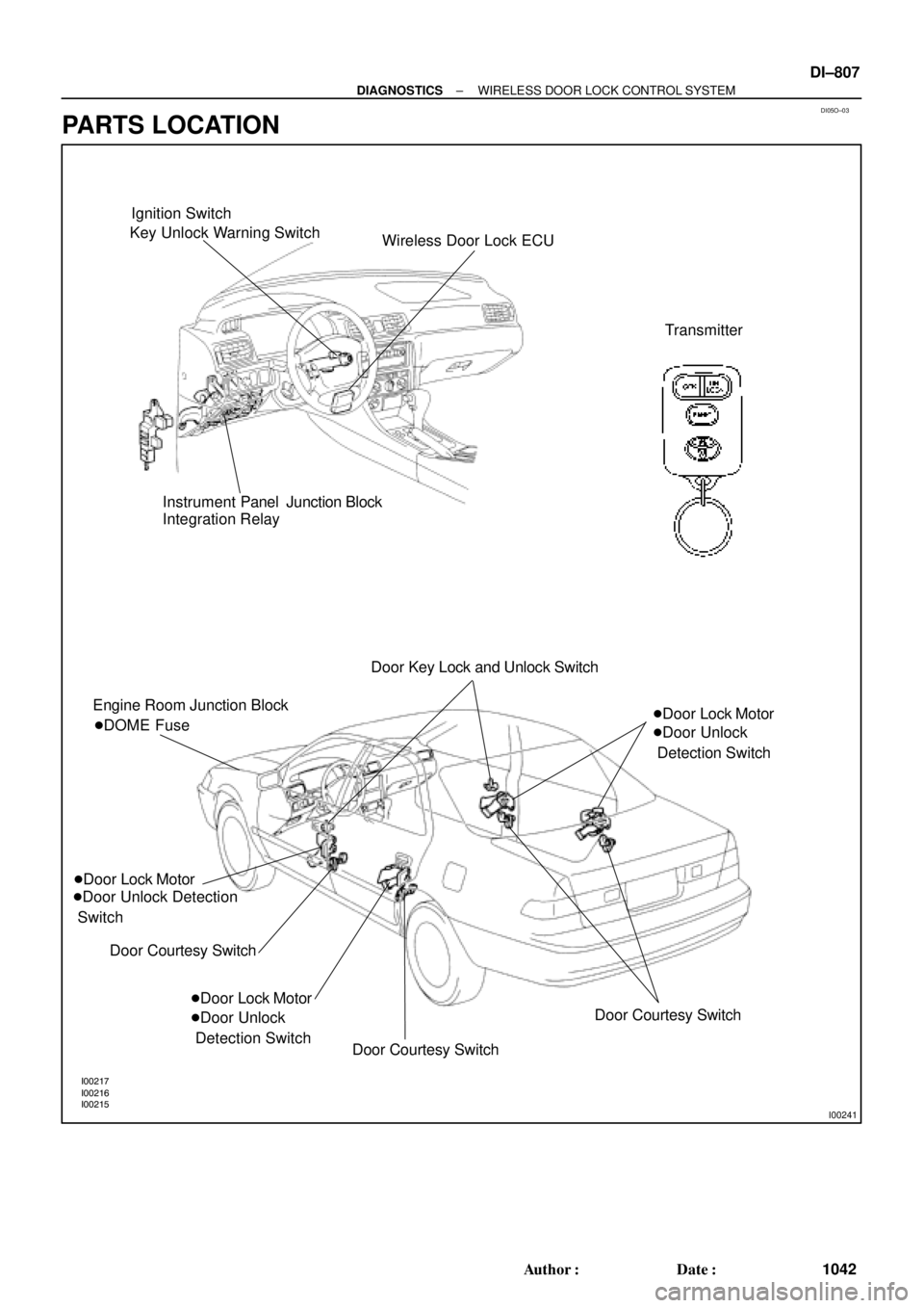
Ignition Switch
Key Unlock Warning Switch
Wireless Door Lock ECU
Transmitter
Instrument Panel Junction Block
Integration Relay
Engine Room Junction Block
�Door Lock Motor
�Door Unlock Detection
Switch
Door Courtesy Switch �DOME FuseDoor Key Lock and Unlock Switch
�Door Lock Motor
�Door Unlock
Detection Switch�Door Lock Motor
�Door Unlock
Detection Switch
Door Courtesy Switch
Door Courtesy Switch
± DIAGNOSTICSWIRELESS DOOR LOCK CONTROL SYSTEM
DI±807
1042 Author�: Date�:
PARTS LOCATION
Page 3235 of 4770

I08426
Wireless Door Lock ECU
Theft Deterrent ECU Integration Relay
UL3 R±G9
T4 I18
UL2 10
T4 UL27
W6R±G R±GI18
B
J6
J/C
3
IE1
74*1
19*25*1
20*2
B
B
B
R±G
R±G
Instrument Panel J/B
1G3
1V
IE 20J37 J/C
RH
J38 W±B
IE1
J/C AA W±B
*3W±B*3
W±B*4
32
UNLOCK LOCK
Door Key
Lock and
Unlock
SwitchLL
L AA
A
3IM1
32
1
UNLOCK LOCK
L
J39
J/C AA W±B
*3W±B*3
W±B*4
20 IM1W±B
1LH
IJ *1: w/o Theft Deterrent System
*2: w/ Theft Deterrent System
*3: TMC Made
*4: TMMK Made
± DIAGNOSTICSWIRELESS DOOR LOCK CONTROL SYSTEM
DI±815
1050 Author�: Date�:
Door Key Lock and Unlock Switch Circuit (Unlock Side)
CIRCUIT DESCRIPTION
The Key±operated switch is built into the door key cylinder. When the key is turned to the lock side, the lock
terminal of the switch is grounded, and when the key is turned to the unlock side the unlock terminal is
grounded.
Furthermore, the door key lock and unlock switch circuit has terminal +B connected inside the theft deterrent
ECU, when neither the lock nor unlock terminal of the key lock and unlock switch are grounded, battery posi-
tive voltage is applied to the door key lock and unlock switch circuit of the wireless door lock ECU.
( Tr inside the ECU coming ON causes the wireless door lock ECU to output a signal to unlock all the doors.)
WIRING DIAGRAM
DI05T±03
Page 3237 of 4770
I08427
Wireless Door Lock ECUIntegration Relay
L2 8
T4 I18
L15
W6
BJ37
J/C
4
IE1
7B
B B
1G3
1V
IE 20RH
J38 W±B
IE1
J/C AA W±B
*3W±B*3
W±B*4
32
UNLOCK LOCK
Door Key
Lock and
Unlock
Switch4
IM1
32
1
UNLOCK LOCK
L±W
J39
J/C A
A W±B
*3W±B*3
W±B*4
20 IM1W±B
1LH
IJ*1: w/o Theft Deterrent System
*2: w/ Theft Deterrent System
*3: TMC Made
*4: TMMK Made
Theft Deterrent ECU
W±B Instrument Panel J/BL±W
L±W
L±W L±W3
*1
18*2
B L±W
L±W
± DIAGNOSTICSWIRELESS DOOR LOCK CONTROL SYSTEM
DI±817
1052 Author�: Date�:
Door Key Lock and Unlock Switch Circuit (Lock Side)
CIRCUIT DESCRIPTION
Refer to page DI±815.
Tr inside the wireless door lock ECU coming ON causes the theft deterrent ECU to output a signal to lock
all the doors.
WIRING DIAGRAM
DI05U±03
Page 3239 of 4770
I00224
Wireless Door Lock ECU
Key Unlock
Warning
SwitchKSW L±B
W±B
1M1J7 5 5
1
2
3 7
IG10
1D
J/C L±B
W±B1M
Integration Relay
Instrument Panel J/BW6 J10 Instrument Panel J/B
L±B B
J9B
J11
A
± DIAGNOSTICSWIRELESS DOOR LOCK CONTROL SYSTEM
DI±819
1054 Author�: Date�:
Key Unlock Warning Switch Circuit
CIRCUIT DESCRIPTION
When the key is inserted in the ignition key cylinder, the key unlock warning switch comes ON, and when
the key is not inserted the switch is OFF.
When the key unlock warning switch is ON, the ECU operates the key confinement prevention function.
WIRING DIAGRAM
DI05V±03