Page 2932 of 4770
F07147
ABS Solenoid RelayGR±R1
IK1
GR±RABS ECU
26
A19R+
34
56
33
3
3 1
2 DLC1Engine Room
R/B No.3
GR
7
2ABS
1
3
W±L
B±G
Fusible Link Block
1
F5 F41
B±G
FL Main
Battery ALT
EAW±B4
A4A18 SR
ABS
Actuator
1
A5
A55
A53
7
A5
A5
A5
A5
A54
8
2
6R±B
W±R11
IK2
IK212R±B
W±R2
A19
A191
A18
A18
A18
A18
A19
A19 L±B
W±L
W±R
R±G
G±Y
LG±B13
IK2
IK255
6
11
12
15
14SFRH
SFRR
SFLH
SFLR
SRRH
SRRR
SRLH
SRLR 3
G±Y
LG±B DI±512
± DIAGNOSTICSANTI±LOCK BRAKE SYSTEM (DENSO Made)
747 Author�: Date�:
WIRING DIAGRAM
Page 2934 of 4770

749 Author�: Date�:
DTC31, 32, 33, 34Speed Sensor Circu")
BR3583
BR3582F00010
RotorSpeed Sensor
Magnet
To ECU
+V
±VHigh Speed
Low Speed
CoilNS
DI±514
± DIAGNOSTICSANTI±LOCK BRAKE SYSTEM (DENSO Made)
749 Author�: Date�:
DTC31, 32, 33, 34Speed Sensor Circuit
CIRCUIT DESCRIPTION
The speed sensor detects wheel speed and sends the ap-
propriate signals to the ECU. These signals are used to control
the ABS system. The front and rear rotors each have 48 serra-
tions.
When the rotors rotate, the magnetic field emitted by the perma-
nent magnet in the speed sensor generates an AC voltage.
Since the frequency of this AC voltage changes in direct propor-
tion to the speed of the rotor, the frequency is used by the ECU
to detect the speed of each wheel.
DTC No.DTC Detecting ConditionTrouble Area
31, 32, 33, 34
Detection of any of conditions from 1. through 4.:
1. Vehicle speed is at 10 km/h (6 mph) or more and the
speed sensor signal circuit is open or short circuit con-
tinues for 15 sec. or more.
2. Momentary interruption of the speed sensor signal oc-
curs 7 times or more.
3. Vehicle speed is at 20 km/h (12mph) or more and inter-
ference on the speed sensor signal continues for 5 sec.
or more.
4. Open circuit condition of the speed sensor signal circuit
continues for 0.5 sec. or more.
�Right front, left front, right rear, left rear speed sensor
�Each speed sensor circuit
�Speed sensor rotor
HINT:
�DTC No. 31 is for the right front speed sensor.
�DTC No. 32 is for the left front speed sensor.
�DTC No. 33 is for the right rear speed sensor.
�DTC No. 34 is for the left rear speed sensor.
Fail safe function:
If trouble occurs in the speed sensor circuit, the ECU cuts off current to the ABS solenoid relay and prohibits
ABS control.
DI1JM±02
Page 2940 of 4770

F07156
Ignition
Switch
W24
AM1
IG1
B±YInstrument Panel J/B
19
1K
ECU±IG1JB±RJ/C
J12
C
CB±R13
A19ABS ECU
IG1
Instrument Panel J/B
21
1K
1B
AM1
B±R
FL Block
1
1
F4 F9
ALT
B±G
FL MAIN
Battery
IG A
Instrument
Panel Brace LH J11
Junction
ConnectorW±B
W±B12
A19
A1925GND1
GND2 DI±520
± DIAGNOSTICSANTI±LOCK BRAKE SYSTEM (DENSO Made)
755 Author�: Date�:
DTC 41 IG Power Source Circuit
CIRCUIT DESCRIPTION
This is the power source for the ECU, hence the actuators.
DTC No.DTC Detecting ConditionTrouble Area
41
Condition 1. or 2. is detected:
1. Vehicle speed is at 3 km/h (1.9 mph) or more and ECU
terminal IG1 voltage is 9.5 V or less , which continues
for 10 sec. or more.
2. When IG1 terminal voltage is less than 9.5 V, there is
open circuit in the motor relay or in the solenoid relay, or
the solenoid circuit malfunction.
�Battery
�Charging system
�Power source circuit
Fail safe function:
If trouble occurs in the power source circuit, the ECU cuts off current to the ABS solenoid relay and prohibits
ABS control.
WIRING DIAGRAM
DI03M±03
Page 2945 of 4770
F07146
B±G
Fusible
Link
Block
F5 1
F4
1
FL
Main B±G
Battery3
3ABSABS Motor
Relay
2 13
43
3
Engine Room R/B No.3GR±R GR±R1
IK126
A19 R+ABS ECU
GR±L1
A18 MR
W±R2
A4
A41
W±B
EAABS Actuator
3
A4R±W10
A18 MT ALT
± DIAGNOSTICSANTI±LOCK BRAKE SYSTEM (DENSO Made)
DI±525
760 Author�: Date�:
DTC 51 ABS Pump Motor Lock
CIRCUIT DESCRIPTION
DTC No.DTC Detecting ConditionTrouble Area
51ABS actuator pump motor is not operating normally.�ABS pump motor
Fail safe function:
If trouble occurs in the ABS pump motor, the ECU cuts off current to the ABS solenoid relay and prohibits
ABS control.
WIRING DIAGRAM
DI4KW±01
Page 2946 of 4770
F03291
(±)
(+)12 A4
DI±526
± DIAGNOSTICSANTI±LOCK BRAKE SYSTEM (DENSO Made)
761 Author�: Date�:
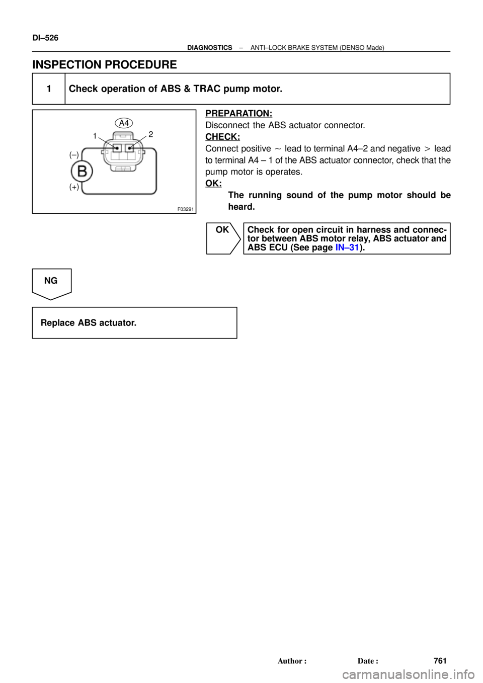
INSPECTION PROCEDURE
1 Check operation of ABS & TRAC pump motor.
PREPARATION:
Disconnect the ABS actuator connector.
CHECK:
Connect positive � lead to terminal A4±2 and negative � lead
to terminal A4 ± 1 of the ABS actuator connector, check that the
pump motor is operates.
OK:
The running sound of the pump motor should be
heard.
OK Check for open circuit in harness and connec-
tor between ABS motor relay, ABS actuator and
ABS ECU (See page IN±31).
NG
Replace ABS actuator.
Page 2947 of 4770
± DIAGNOSTICSANTI±LOCK BRAKE SYSTEM (DENSO Made)
DI±527
762 Author�: Date�:
DTC Always ON ABS ECU Malfunction
CIRCUIT DESCRIPTION
DTC No.DTC Detecting ConditionTrouble Area
Always ONABS ECU internal malfunction is detected.�ECU
�Battery
Fail safe function:
If trouble occurs in the power source circuit, the ECU cuts off current to the ABS solenoid relay and prohibits
ABS control.
INSPECTION PROCEDURE
1 Is DTC output?
Check DTC on page DI±493.
YES Repair circuit indicated by the code output.
NO
2 Is normal code displayed?
YES Check ABS solenoid relay. Check for short cir-
cuit in harness and connector between ABS so-
lenoid relay and DLC1 (See page IN±31).
NO
3 Is ABS warning light go off?
YES Check for open or short circuit in harness and
connector between ECU±IG fuse and ABS ECU
(See page IN±31).
NO
DI03P±04
Page 2949 of 4770

F07217
Engine Room R/B No. 3
ABS Solenoid Relay
3
ABS
Actuator
A4 1
2
5 BatteryGAUGE Instrument Panel J/B
J/C
J4
D
ABS ECU 33 3 3
EA34 6
ABS ECUD
IK28
R±L
II3 4
DLC1 R±L
G±B
II3 5 Short
Pin
W±B
ABS ECU W±L
G±B
C
CC R±L
R±L 1D2
7
4
R±L
A19WA IG3 12
11 G±B 4
G±B C10
C10
J/C
J29ABS Warning
Light
23
22 R±L
± DIAGNOSTICSANTI±LOCK BRAKE SYSTEM (DENSO Made)
DI±529
764 Author�: Date�:
ABS Warning Light Circuit
CIRCUIT DESCRIPTION
If the ECU detects trouble, it lights the ABS warning light while at the same time prohibiting ABS control. At
this time, the ECU records a DTC in memory.
After removing the short pin of the DLC1, connect terminals Tc and E
1 of the DLC1 or DLC2 to make the
ABS warning light blink and output the DTC.
WIRING DIAGRAM
INSPECTION PROCEDURE
Troubleshooting in accordance with the chart below for each trouble symptom.
ABS warning light does not light upGo to step 1
ABS warning light remains onGo to step 3
1 Check ABS warning light.
See combination meter troubleshooting on page BE±2.
NG Repair bulb or combination meter assembly.
OK
DI03Q±03
Page 2950 of 4770
(±)
(+) (±)1 2 3
4 5 6 Continuity
DI±530
± DIAGNOSTICSANTI±LOCK BRAKE SYSTEM (DENSO Made)
765 Author�: Date")
F00043
1 2 3
4 5 6
1 2 3
4 5 6
1 2 3
4
65 Open
Continuity
Continuity
Continuity
Open
(+)(±)
(+) (±)1 2 3
4 5 6 Continuity
DI±530
± DIAGNOSTICSANTI±LOCK BRAKE SYSTEM (DENSO Made)
765 Author�: Date�:
2 Check ABS solenoid relay.
PREPARATION:
Remove ABS solenoid relay from Engine Room R/B No. 3.
CHECK:
Check continuity between each terminal of ABS solenoid relay.
OK:
Terminals 4 and 6Continuity (Reference value 80 W)
Terminals 2 and 3Continuity
Terminals 1 and 3Open
CHECK:
(a) Apply battery positive voltage between terminals 4 and 6.
(b) Check continuity between each terminal of ABS solenoid
relay.
OK:
Terminals 2 and 3Open
Terminals 1 and 3Continuity
CHECK:
Connect the � test lead to terminal 5 and the � lead to terminal
3. Check continuity between the terminals.
OK:
Continuity
If there is no continuity, connect the � test lead to terminal 5
and the � lead to terminal 3. Recheck continuity between ter-
minals.
NG Replace ABS solenoid relay.
OK
Check for open circuit in harness and connector between DLC1, ABS solenoid relay and body
ground (See page IN±31).