Page 2983 of 4770
± DIAGNOSTICSANTI±LOCK BRAKE SYSTEM (BOSCH Made)
DI±563
798 Author�: Date�:
DTC 62 ABS ECU Malfunction
CIRCUIT DESCRIPTION
DTC No.DTC Detecting ConditionTrouble Area
62ABS ECU continuously detects the proper operation of
ABS.�Battery
�ECU
Fail safe function:
If trouble occurs in the power source circuit, the ECU cuts off current to the ABS solenoid valve relay and
prohibits ABS control.
INSPECTION PROCEDURE
1 Is DTC output?
Check DTC on page DI±539.
YES Repair circuit indicated by the code output.
NO
2 Is normal code displayed?
YES Check for short circuit in harness and connec-
tor between DLC1 or DLC2 and ABS ECU
(See page IN±31).
NO
3 Does ABS warning light go off?
YES Check for open and short circuit in harness and
connector of Tc circuit between ECU and DLC2
or DLC1.
NO
DI047±06
Page 2998 of 4770

DI04F±04
DI±578
± DIAGNOSTICSABS & TRACTION CONTROL SYSTEM
813 Author�: Date�:
DIAGNOSTIC TROUBLE CODE CHART
HINT:
�Using SST 09843 ±18020, connect the terminals Tc and E1.
�If a malfunction code is displayed during the DTC check, check the circuit listed for the code. For details
of each code, turn to the page referred to under the ºSee pageº for respective ºDTC No.º in the DTC
chart.
DTC No.
(See Page)Detection ItemTrouble Area
11
(DI±584)Open circuit in ABS & TRAC solenoid relay circuit�ABS & TRAC solenoid relay
ABS & TRAC l id l i it12
(DI±584)Short circuit in ABS & TRAC solenoid relay circuit
�ABS & TRAC solenoid relay circuit
�ECU
13
(DI±587)Open circuit in ABS & TRAC motor relay circuit�ABS & TRAC motor relay
ABS & TRAC t l i it14
(DI±587)Short circuit in ABS & TRAC motor relay circuit
�ABS & TRAC motor relay circuit
�ECU
21
(DI±590)Open or short circuit in right front solenoid circuit
�ABS & TRAC actuator
�SFRR or SFRH circuit
�ECU
22
(DI±590)Open or short circuit in left front solenoid circuit
�ABS & TRAC actuator
�SFLR or SFLH circuit
�ECU
23
(DI±590)Open or short circuit in right rear solenoid circuit
�ABS & TRAC actuator
�SRRR or SRRH circuit
�ECU
24
(DI±590)Open or short circuit in left rear solenoid circuit
�ABS & TRAC actuator
�SRLR or SRLH circuit
�ECU
25
(DI±590)Open or short circuit in SMC1 circuit
�ABS & TRAC actuator
�SMC1 circuit
�ECU
26
(DI±590)Open or short circuit in SMC2 circuit
�ABS & TRAC actuator
�SMC2 circuit
�ECU
27
(DI±590)Open or short circuit in SRC1 circuit
�ABS & TRAC actuator
�SRC1 circuit
�ECU
28
(DI±590)Open or short circuit in SRC2 circuit
�ABS & TRAC actuator
�SRC2 circuit
�ECU
31
(DI±593)Right front wheel speed sensor signal malfunction
32
(DI±593)Left front wheel speed sensor signal malfunction�Right front, left front, right rear and left rear speed sensor
�Each speed sensor circuit
33
(DI±593)Right rear wheel speed sensor signal malfunction
�Each s eed sensor circuit
�Speed sensor rotor
�ECU
34
(DI±593)Left rear wheel speed sensor signal malfunction
41
(DI±598)Low battery positive voltage or abnormally high battery
positive voltage
�Battery
�Charging system
�Power source circuit
�ECU
Page 3000 of 4770
DI04G±04
F01177
SLIP Indicator Light
TRAC OFF Indicator Light
ABS Warning Light
DLC1
DLC2
Rear Speed Sensor
Sensor Rotor ABS & TRAC ActuatorABS & TRAC ECU
TRAC OFF Switch
ABS & TRAC
Solenoid Relay
ABS & TRAC
Motor RelaySensor Rotor
Front Speed Sensor
Stop Light Switch Front Speed Sensor
DI±580
± DIAGNOSTICSABS & TRACTION CONTROL SYSTEM
815 Author�: Date�:
PARTS LOCATION
Page 3004 of 4770

DI04J±04
F03951
ABS & TRAC Solenoid Relay
Battery
MAINB±G1F4 ALT1F5 B±G
FL
BlockW±B
EA 3 ABS
12
3 Engine Room R/B No. 3
1
2
336
4
53
3
3
W±L
A8
4ABS & TRAC
Actuator
ABS & TRAC
ECU
5
A8R
A1510
AST GR
GR±RABS & TRAC
ECU
11
A15
1
A15SR
R+
DLC1 DI±584
± DIAGNOSTICSABS & TRACTION CONTROL SYSTEM
819 Author�: Date�:
CIRCUIT INSPECTION
DTC 11, 12 ABS & TRAC Solenoid Relay Circuit
CIRCUIT DESCRIPTION
This relay supplies power to each ABS & TRAC solenoid. After the ignition switch is turned ON, if the initial
check is OK, the relay goes on.
DTC No.DTC Detecting ConditionTrouble Area
11
Condition 1. to 3. are detected:
1. Malfunction of solenoid relay monitor
2. Battery voltage will not exceed more than 17.0 V within
2.16 sec.
3. Battery voltage will not become less than 9.5 V within
2.16 sec., or after the solenoid relay is ON and AST
voltage of ECU terminal does not become 8.0 V or more.
�ABS & TRAC solenoid relay
�ABS & TRAC solenoid relay circuit
�ECU
12
Solenoid relay is OFF in the midst of premain routine, and
AST voltage of ECU terminal is 8.0 V or more, which con-
tinues for 2.04 sec. or more.
Fail safe function:
If any trouble occurs in the ABS & TRAC solenoid relay circuit, the ECU cuts off current to the ABS & TRAC
solenoid relay and prohibits ABS control and TRAC control.
WIRING DIAGRAM
Page 3005 of 4770
(±)
(+)(±)
(+)(±)(+)(±)
123
456
Engine Room R/B No. 3
F00055
ABS & TRAC
Solenoid
Relay
A15
AST
4
5
ABS & TRAC
Actuator
ECU
ABS & TRAC
Solenoid
Relay
A15
AST
4
5
ABS & TRAC
Actuator
ECU
A")
F00182
(+)(±)
(+)(±)
(+)(±)(+)(±)
123
456
Engine Room R/B No. 3
F00055
ABS & TRAC
Solenoid
Relay
A15
AST
4
5
ABS & TRAC
Actuator
ECU
ABS & TRAC
Solenoid
Relay
A15
AST
4
5
ABS & TRAC
Actuator
ECU
ABS & TRAC
Solenoid
Relay
A15
AST
4
5
ABS & TRAC
Actuator
ECU
ABS & TRAC
Solenoid
Relay3
A8
A8
A15
AST
4
5
ABS & TRAC
Actuator
ECUEngine Room R/B No. 3
± DIAGNOSTICSABS & TRACTION CONTROL SYSTEM
DI±585
820 Author�: Date�:
INSPECTION PROCEDURE
1 Check voltage between terminals 1 and 2 of Engine Room R/B No. 3 (for ABS &
TRAC solenoid relay).
PREPARATION:
Remove ABS & TRAC solenoid relay from Engine Room R/B
No. 3.
CHECK:
Measure the voltage between terminals 1 and 2 of Engine
Room R/B No. 3 (for ABS & TRAC solenoid relay).
OK:
Voltage: 10 ± 14 V
NG Check and repair harness or connector.
OK
2 Check continuity between terminal 3 of ABS & TRAC solenoid relay and terminal
AST of ABS & TRAC ECU.
CHECK:
Check continuity between terminal 3 of Engine Room R/B No.
3 (for ABS solenoid relay) and terminal AST of ABS & TRAC
ECU.
OK:
Continuity
HINT:
There is a resistance of 4 ~ 6 W between terminals A8 ± 4 and
A8 ± 5 of ABS actuator.
NG Repair or replace harness or ABS & TRAC
actuator.
OK
Page 3006 of 4770
F00042
1
2 3
4 5 6
1 2 3
4 5 6
1 2 3
4 5 6 Open
Continuity
Continuity
Open Continuity
(+) (±)
DI±586
± DIAGNOSTICSABS & TRACTION CONTROL SYSTEM
821 Author�: Date�:
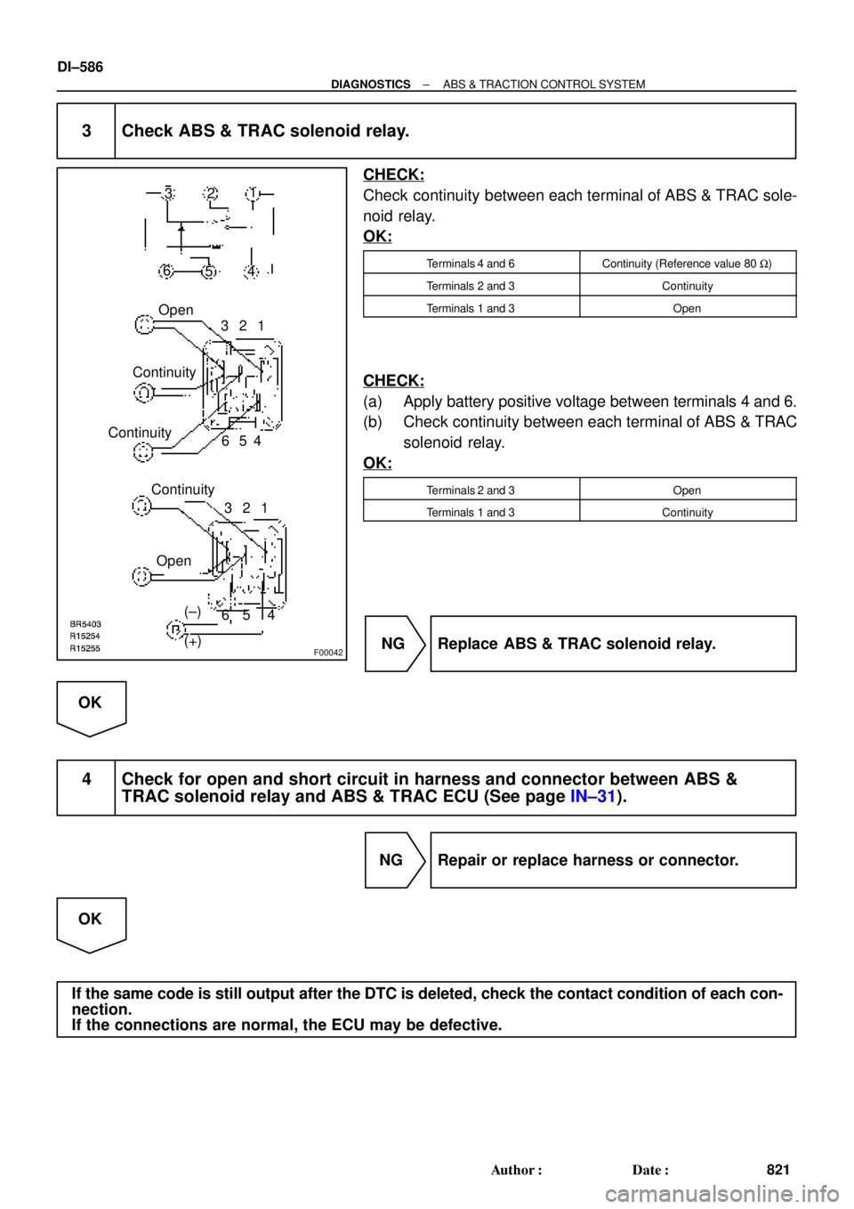
3 Check ABS & TRAC solenoid relay.
CHECK:
Check continuity between each terminal of ABS & TRAC sole-
noid relay.
OK:
Terminals 4 and 6Continuity (Reference value 80 W)
Terminals 2 and 3Continuity
Terminals 1 and 3Open
CHECK:
(a) Apply battery positive voltage between terminals 4 and 6.
(b) Check continuity between each terminal of ABS & TRAC
solenoid relay.
OK:
Terminals 2 and 3Open
Terminals 1 and 3Continuity
NG Replace ABS & TRAC solenoid relay.
OK
4 Check for open and short circuit in harness and connector between ABS &
TRAC solenoid relay and ABS & TRAC ECU (See page IN±31).
NG Repair or replace harness or connector.
OK
If the same code is still output after the DTC is deleted, check the contact condition of each con-
nection.
If the connections are normal, the ECU may be defective.
Page 3007 of 4770

F03413
Battery2
Engine Room R/B No. 3
MAIN B±G F4F5
FL
BlockABS
12
3
1ALT1
31 B±GABS & TRAC
Motor Relay
4
33
3GR±L
GR±R24
A15
1
A15ABS & TRAC ECU
MR
R+
MT
A1514
R±W
A83 ABS & TRAC Actuator
W±R2
A8
1
A8
W±B
EA
± DIAGNOSTICSABS & TRACTION CONTROL SYSTEM
DI±587
822 Author�: Date�:
DTC 13, 14 ABS & TRAC Motor Relay Circuit
CIRCUIT DESCRIPTION
The ABS & TRAC motor relay supplies power to the ABS & TRAC pump motor. While the ABS is activated,
the ECU switches the ABS & TRAC motor relay ON and operates the ABS & TRAC pump motor.
DTC No.DTC Detecting ConditionTrouble Area
13
Conditions 1. to 3. are detected:
1. Malfunction of motor relay monitor
2. Battery voltage will not exceed more than 17.0 V within
2.16 sec.
3. Battery voltage will not become less than 9.5 V within
2.16 sec., or after the motor relay is ON and motor relay
monitor does not ON.
�ABS & TRAC motor relay
�ABS & TRAC motor relay circuit
�ECU
14Motor relay is OFF, and motor relay monitor is ON , which
continues for 20.16 sec. or more.
Fail safe function:
If any trouble occurs in the ABS & TRAC motor relay circuit, the ECU cuts off current to the ABS & TRAC
solenoid relay and prohibits ABS control and TRAC control.
WIRING DIAGRAM
DI04K±04
Page 3008 of 4770
 (±)
Engine Room
R/B No. 31
2
34 (+) (±)
Engine Room
R/B No. 31
2
34 (+) (±)
Engine Room
R/B No. 31
2
34 (+) (±)
Engine Room
R/B No. 3
F00056
ABS & TRAC
Motor
Relay
M2
A15
MT")
F00049
1
2
34 (+) (±)
Engine Room
R/B No. 31
2
34 (+) (±)
Engine Room
R/B No. 31
2
34 (+) (±)
Engine Room
R/B No. 31
2
34 (+) (±)
Engine Room
R/B No. 3
F00056
ABS & TRAC
Motor
Relay
M2
A15
MT
32
2
3
ABS & TRAC
Actuator
ECU
ABS & TRAC
Motor
Relay
M2
A15
MT
32
2
3
ABS & TRAC
Actuator
ECU
ABS & TRAC
Motor
Relay
M2
A15
MT
32
2
3
ABS & TRAC
Actuator
ECU
A8
ABS & TRAC
Motor
Relay
A8 M2
A15
MT
32
2
3
ABS & TRAC
Actuator
ECUEngine Room R/B
No. 3
DI±588
± DIAGNOSTICSABS & TRACTION CONTROL SYSTEM
823 Author�: Date�:
INSPECTION PROCEDURE
1 Check voltage between terminal 1 of Engine Room R/B No. 3 (for ABS & TRAC
motor relay) and body ground.
PREPARATION:
Remove ABS & TRAC motor relay from Engine Room R/B No.
3.
CHECK:
Measure voltage between terminal 1 of Engine Room R/B No.
3 (for ABS & TRAC motor relay) and body ground.
OK:
Voltage: 10 ± 14 V
NG Check and repair harness or connector.
OK
2 Check continuity between terminal 2 of ABS & TRAC motor relay and terminal
MT of ABS & TRAC ECU.
CHECK:
Check continuity between terminal 2 of Engine Room R/B No.
3 (for ABS & TRAC motor relay) and terminal MT of ABS &
TRAC ECU.
OK:
Continuity
HINT:
There is a resistance of 4 ~ 6 W between terminals A8 ± 2 and
A8 ± 3 of ABS & TRAC actuator.
NG Repair or replace harness or ABS & TRAC
actuator.
OK