Page 2800 of 4770
A00306
135
24 6 IACVIACV closed (VSV: ON)
Throttle Valve30°
3,700 rpm
Engine speed
Throttle valve
opening angle
FI7011 FI6570
A07452
From Battery 2J2
W±B
B±Y
J20
Junction
Connector 9
AAECMACIS
12
MRELB±W
VSV for ACIS
R±Y B±Y 17
2K
2A 2F
51 2
3 4Engine Room J/B
EFI
EBJunction
Connector BB+
B±Y178
E11E7
B
B±YE01
B±W
J36 J35CC
EFI Relay
J27 J28
II3Junction Connector DI±380
± DIAGNOSTICSENGINE (1MZ±FE)
615 Author�: Date�:
IACV Control VSV Circuit
CIRCUIT DESCRIPTION
This circuit opens and closes the IACV (Intake Air Control Valve) in response to the engine load in order to
increase the intake efficiency (ACIS: Acoustic Control Induction System).
When the engine speed is 3,700 rpm or less and the throttle valve opening angle is 60° or more, the ECM
turns the VSV ON and closes the IACV. At all other times, the VSV is OFF, so the IACV is open.
WIRING DIAGRAM
DI08E±06
Page 2802 of 4770
A02041
ON
ACIS (+)
DI±382
± DIAGNOSTICSENGINE (1MZ±FE)
617 Author�: Date�:
3 Check for open and short in harness and connector between EFI main relay
(Marking: EFI) and ECM (See page IN±31).
NG Repair or replace harness or connector.
OK
Check and replace ECM (See page IN±31).
OBD II scan tool (excluding TOYOTA hand±held tester)
1 Check VSV for ACIS (See page SF±60).
NG Replace VSV for ACIS.
OK
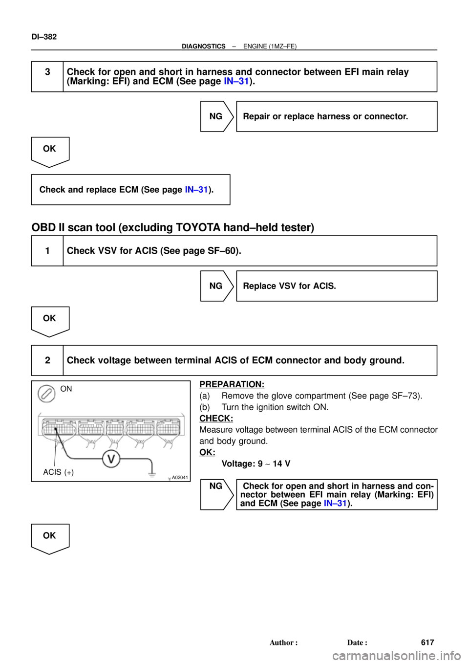
2 Check voltage between terminal ACIS of ECM connector and body ground.
PREPARATION:
(a) Remove the glove compartment (See page SF±73).
(b) Turn the ignition switch ON.
CHECK:
Measure voltage between terminal ACIS of the ECM connector
and body ground.
OK:
Voltage: 9 ~ 14 V
NG Check for open and short in harness and con-
nector between EFI main relay (Marking: EFI)
and ECM (See page IN±31).
OK
Page 2804 of 4770

A07453
5
1B±R
1ECM Engine Room J/B
E77
STA
E1 S2
Starter W±B 9 5
2D
2K 3
2
Sarter Relay MAIN
2B3
2J 11 B
J7
J7 J8
Junction
Connector CB
B II210 From Battery
W±B
W±B
A
A J11
Junction
Connector
IG Instrument
Panel J/B
STARTER
From Ignition Switch11
II2
B±W(A/T)
B±W(A/T)
B±W
Park/Neutral
Position Switch 6
5
B±W(A/T)
B
B
B
1J
1K 3
4
B±W(M/T)
12
Clutch Start Switch
GR
*1GR1
*1B±O
*GR
*GR
*GR
*B±O(M/T)
J16
Junction
Connector
*B±O
*: TMMK made
*
1: TMC made
*1B±O
DI±384
± DIAGNOSTICSENGINE (1MZ±FE)
619 Author�: Date�:
Starter Signal Circuit
CIRCUIT DESCRIPTION
When the engine is cranked, the intake air flow is slow, so fuel vaporization is poor. A rich mixture is therefore
necessary in order to achieve good startability. While the engine is being cranked, the battery positive volt-
age is applied to terminal STA of the ECM. The starter signal is mainly used to increase the fuel injection
volume for the starting injection control and after±start injection control.
WIRING DIAGRAM
DI08B±06
Page 2805 of 4770
± DIAGNOSTICSENGINE (1MZ±FE)
DI±385
620 Author�: Date�:
INSPECTION PROCEDURE
HINT:
This diagnostic chart is based on the premise that the engine is cranked normally. If the engine is not
cranked, proceed to the problem symptoms table on page DI±221.
TOYOTA hand±held tester
1 Connect TOYOTA hand±held tester, and check STA signal.
PREPARATION:
(a) Connect the TOYOTA hand±held tester to the DLC3.
(b) Turn the ignition switch ON and push the TOYOTA hand±held tester main switch ON.
CHECK:
Read STA signal on the TOYOTA hand±held tester while starter operates.
OK:
Ignition switch positionONSTART
STA signalOFFON
OK Proceed to next circuit inspection shown on
problem symptom table (See page DI±221).
NG
2 Check for open in harness and connector between ECM and starter relay
(See page IN±31).
NG Repair or replace or connector.
OK
Check and replace ECM (See page IN±31).
Page 2806 of 4770
A07152
ON
STA (+)
DI±386
± DIAGNOSTICSENGINE (1MZ±FE)
621 Author�: Date�:
OBD II scan tool (excluding TOYOTA hand±held tester)
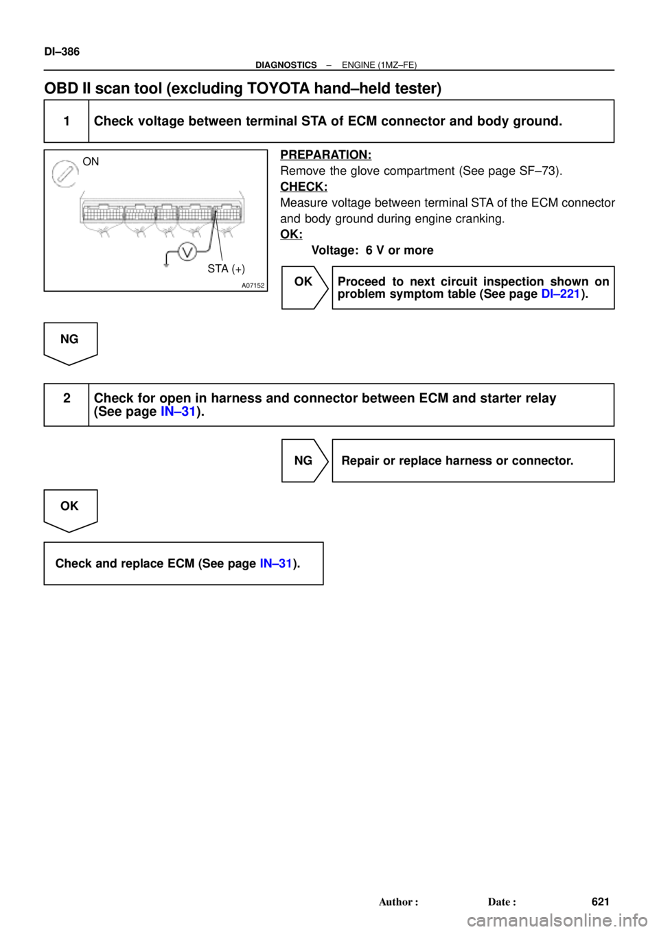
1 Check voltage between terminal STA of ECM connector and body ground.
PREPARATION:
Remove the glove compartment (See page SF±73).
CHECK:
Measure voltage between terminal STA of the ECM connector
and body ground during engine cranking.
OK:
Voltage: 6 V or more
OK Proceed to next circuit inspection shown on
problem symptom table (See page DI±221).
NG
2 Check for open in harness and connector between ECM and starter relay
(See page IN±31).
NG Repair or replace harness or connector.
OK
Check and replace ECM (See page IN±31).
Page 2826 of 4770

641 Author�: Date�:
2. Chapter 2: On±Vehicle Repair
(�: A140E AUTOMATIC TRANSAXLE Repair Manual Pub. No. RM385U)
SymptomSuspect AreaSee page
Vehicle")
DI±406
± DIAGNOSTICSAUTOMATIC TRANSAXLE (A140E)
641 Author�: Date�:
2. Chapter 2: On±Vehicle Repair
(�: A140E AUTOMATIC TRANSAXLE Repair Manual Pub. No. RM385U)
SymptomSuspect AreaSee page
Vehicle does not move in any forward positions and reverse posi-
tion
1. Manual valve
2. Throttle valve
3. Primary regulator valve
4. Off±vehicle repair matrix chart�
�
�
±
Vehicle does not move in R position1. Off±vehicle repair matrix chart±
No up±shift (1st " 2nd)1. 1±2 shift valve
2. Off±vehicle repair matrix chart�
±
No up±shift (2nd " 3rd)1. 2±3 shift valve
2. Off±vehicle repair matrix chart�
±
No up±shift (3rd " O/D)1. 3±4 shift valve
2. Off±vehicle repair matrix chart�
±
No down±shift (O/D " 3rd)1. 3±4 shift valve�
No down±shift (3rd " 2nd)1. 2±3 shift valve�
No down±shift (2nd " 1st)1. 1±2 shift valve�
No lock±up or No lock±up off1. Lock±up relay valve
2. Off±vehicle repair matrix chart�
±
Harsh engagement (N " D)1. C1 accumulator
2. Off±vehicle repair matrix chart�
±
Harsh engagement (N " R)1. C2 accumulator
2. Off±vehicle repair matrix chart�
±
Harsh engagement (N " L)1. Low coast modulator valve�
Harsh engagement (Lock±up)1. Lock±up relay valve
2. Off±vehicle repair matrix chart�
±
Harsh engagement (1st " 2nd " 3rd " O/D)
1. Throttle modulator valve
2. Cut back valve
3. Throttle valve�
�
�
Harsh engagement (2nd " 3rd)1. C2 accumulator�
Harsh engagement (3rd " O/D)1. B0 accumulator�
Harsh engagement (O/D " 3rd)1. C0 accumulator
2. B
0 accumulator
�
�
Slip or shudder (Forward and reverse)
1. Throttle valve
2. Oil strainer
3. Off±vehicle repair matrix chart�
�
±
No engine braking (1st: L position)1. Low coast modulator valve
2. Off±vehicle repair matrix chart�
±
No engine braking (2nd: 2 position)1. 2nd coast modulator valve
2. Off±vehicle repair matrix chart�
±
No kick±down
1. 1±2 shift valve
2. 2±3 shift valve
3. 3±4 shift valve�
�
�
Page 2839 of 4770
D01808
1
E3P
*1
Transaxle
Shift Solenoid
Valve SLECM
B+
: w/ Engine Immobiliser System
: w/o Engine Immobiliser SystemSL
E91 20
*1
*2
E9
*2
± DIAGNOSTICSAUTOMATIC TRANSAXLE (A140E)
DI±419
654 Author�: Date�:
DTC P0773 Shift Solenoid E Electrical Malfunction
(Shift Solenoid Valve SL)
CIRCUIT DESCRIPTION
The shift solenoid valve SL is turned ON and OFF by signals from the ECM to control the hydraulic pressure
acting on the lock±up relay valve, which then controls operation of the lock±up clutch.
Fail safe function
If the ECM detects a malfunction, it turns the shift solenoid valve SL OFF.
DTC No.DTC Detecting ConditionTrouble Area
P0773
Either (a) or (b) is detected for 1 time.(2 trip detection logic)
(a) Solenoid resistance is 8 W or less short circuit when sole-
noid is energized.
(b) Solenoid resistance is 100 kW or more open circuit when
solenoid is not energized.
�Open or short in shift solenoid valve SL circuit
�Shift solenoid valve SL
�ECM
WIRING DIAGRAM
DI035±02
Page 2845 of 4770

D01820
Combination
Meter
R
C8R ± B
13
IG13
2
L8
11
6 C8
C8O
Y16
IG13
*3 L ± W
*4 O
1HInstrument
Panel J/BECM
1V Park/Neutral
Position Switch
P1
L ± W
B ± WII2
E
8 34
P1
P1 P12Y
R ± BII2
J29
Junction
Connector E
E
Y10
5
Y19
15
*1
*2
E7
E7
E7
E7
E7
E7R2 L
1816
*1
*2
17
22B
+
NSW *3 L ± W
*4 O
R ± B
R ± B
B ± W
DD
D
J29
Junction
Connector
J27J27
J28 CC
A
R ± B
B ± W 5
6
3
11II3
II2
B
BB R ± L A
A
J21
Junction
Connector
J28
Junction
Connector
5 2II2R ± L
F
F6
B ± R
F9
ALT
B ± G
B ± R
1
112F9
F4F6
FL
MAIN
BatteryAM1
1B
2L12
55 1B
1K1K
2A 41
AM2 W ± R
B GR
II2
W ± R
10*5
*6GR
B ± O
C
J8B*5
*6GR
B ± O
BW2
74
8 I16 I16
I16 I16Ignition Switch
B ± Y
R11
43 1K
1K1J
1J GAUGE
STARTER
MAINST Relay
2BB ± W
3
115
9
2J2D
2K 5
3
12 Y
J29
Junction
Connector
J27, J28
Junction Connector
*3 L ± W
*4 O
Instrument Panel J/B
Instrument Panel J/B Instrument Panel J/B
Engine Room J/B No.2
J11 Junction Connector
*1: w/ Engine Immobiliser System
*2: w/o Engine Immobiliser System
*3: TMC Made*4: TMMK Made
*5: TMC Made w/o Traction Control
*6: Except TMC Made w/o Traction ControlInstrument Panel J/B
Starter
J7A
IK R ± L
J7 J8 Junction Connector Engine Room J/B No.2 R ± L
± DIAGNOSTICSAUTOMATIC TRANSAXLE (A140E)
DI±425
660 Author�: Date�:
WIRING DIAGRAM

Throttle Valve30°
3,700 rpm
Engine speed
Throttle valve
opening angle
FI7011 FI6570
A07452
From Battery 2J2
W±B
B±Y
J20
Junction
Connector 9
AAECMACIS
12")

DI±419
654 Author")