Page 2742 of 4770
DI±322
± DIAGNOSTICSENGINE (1MZ±FE)
557 Author�: Date�:
8 Check operation of VSV for EVAP (See page SF±58).
OK Go to step 9.
NG
Replace VSV and charcoal canister, and then clean the vacuum hoses between throttle body and
VSV for EVAP, and VSV for EVAP and charcoal canister.
9 Check for open and short in harness and connector between EFI main relay
(Marking: EFI) and VSV for EVAP, VSV for EVAP and ECM (See page IN±31).
NG Repair or replace harness or connector.
OK
Check and replace ECM (See page IN±31).
Page 2744 of 4770
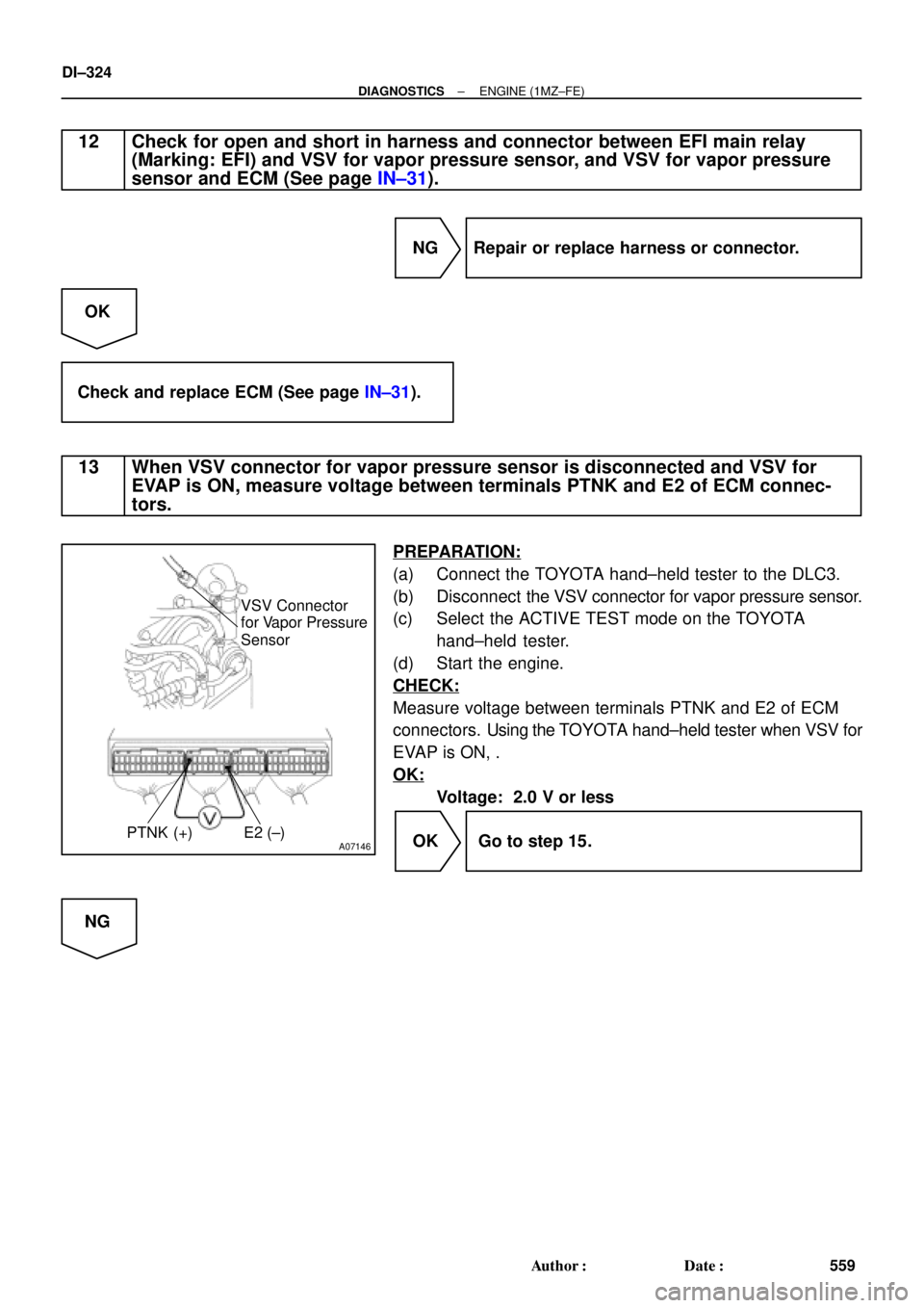
A07146PTNK (+) E2 (±)
VSV Connector
for Vapor Pressure
Sensor
DI±324
± DIAGNOSTICSENGINE (1MZ±FE)
559 Author�: Date�:
12 Check for open and short in harness and connector between EFI main relay
(Marking: EFI) and VSV for vapor pressure sensor, and VSV for vapor pressure
sensor and ECM (See page IN±31).
NG Repair or replace harness or connector.
OK
Check and replace ECM (See page IN±31).
13 When VSV connector for vapor pressure sensor is disconnected and VSV for
EVAP is ON, measure voltage between terminals PTNK and E2 of ECM connec-
tors.
PREPARATION:
(a) Connect the TOYOTA hand±held tester to the DLC3.
(b) Disconnect the VSV connector for vapor pressure sensor.
(c) Select the ACTIVE TEST mode on the TOYOTA
hand±held tester.
(d) Start the engine.
CHECK:
Measure voltage between terminals PTNK and E2 of ECM
connectors. Using the TOYOTA hand±held tester when VSV for
EVAP is ON, .
OK:
Voltage: 2.0 V or less
OK Go to step 15.
NG
Page 2749 of 4770
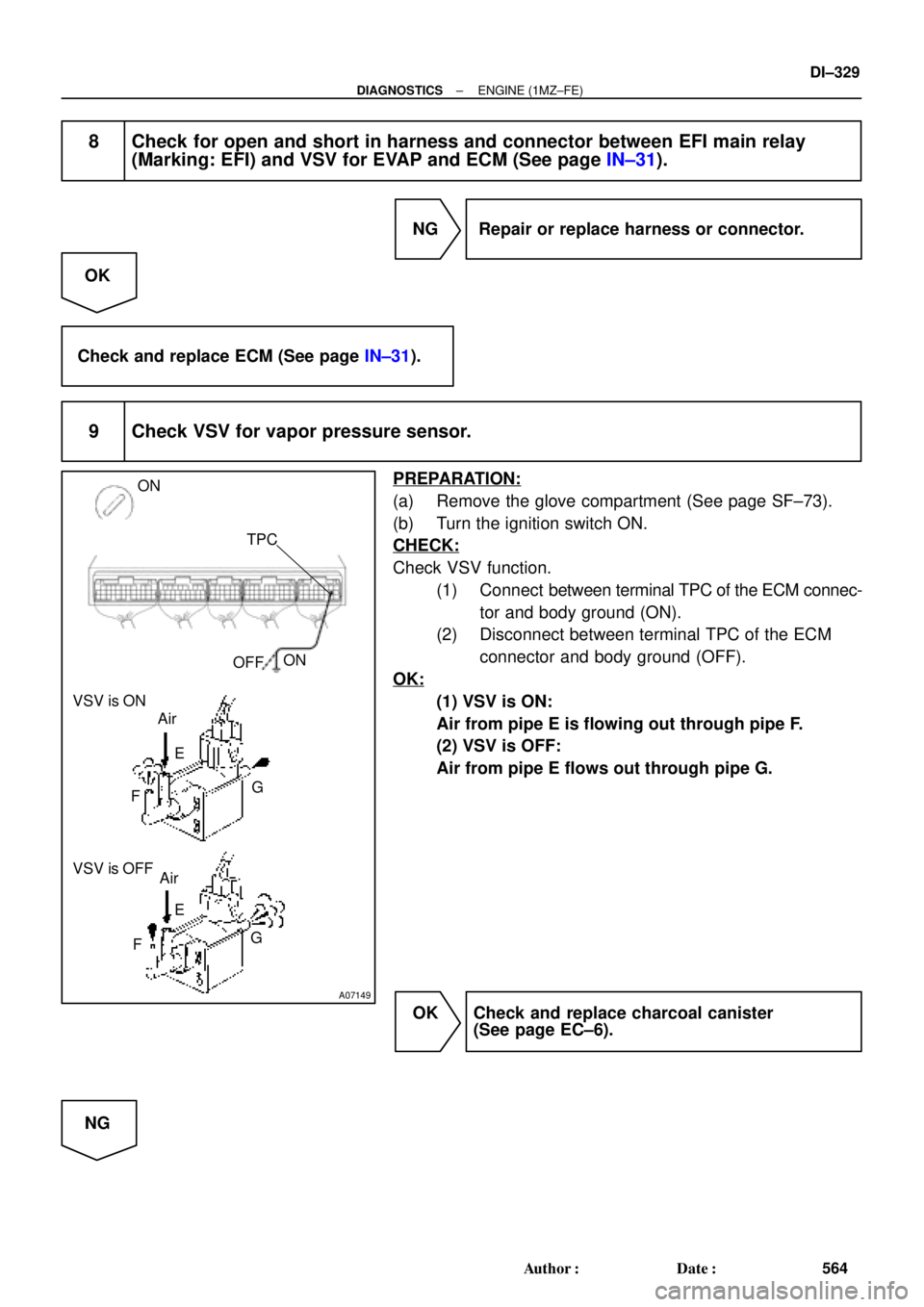
A07149
ON
TPC
OFFON
VSV is ON
VSV is OFF
Air
E
FG Air
G E
F
± DIAGNOSTICSENGINE (1MZ±FE)
DI±329
564 Author�: Date�:
8 Check for open and short in harness and connector between EFI main relay
(Marking: EFI) and VSV for EVAP and ECM (See page IN±31).
NG Repair or replace harness or connector.
OK
Check and replace ECM (See page IN±31).
9 Check VSV for vapor pressure sensor.
PREPARATION:
(a) Remove the glove compartment (See page SF±73).
(b) Turn the ignition switch ON.
CHECK:
Check VSV function.
(1) Connect between terminal TPC of the ECM connec-
tor and body ground (ON).
(2) Disconnect between terminal TPC of the ECM
connector and body ground (OFF).
OK:
(1) VSV is ON:
Air from pipe E is flowing out through pipe F.
(2) VSV is OFF:
Air from pipe E flows out through pipe G.
OK Check and replace charcoal canister
(See page EC±6).
NG
Page 2750 of 4770
DI±330
± DIAGNOSTICSENGINE (1MZ±FE)
565 Author�: Date�:
10 Check operation of VSV for vapor pressure sensor (See page SF±62).
OK Go to step 11.
NG
Replace VSV and clean the vacuum hoses between charcoal canister and VSV for vapor pressure
sensor, and VSV for vapor pressure sensor and vapor pressure sensor, and then check the char-
coal canister.
11 Check for open and short in harness and connector between EFI main relay
(Marking: EFI) and VSV for vapor pressure sensor, and VSV for vapor pressure
sensor and ECM (See page IN±31).
NG Repair or replace harness or connector.
OK
Check and replace ECM (See page IN±31).
12 Check the fuel tank over fill check valve (See page EC±6).
NG Replace fuel tank over fill check valve or fuel
tank.
OK
Check and replace charcoal canister
(See page EC±6).
Page 2756 of 4770

P01559
Throttle Valve
From
Air
Cleaner
Signal
ECM
ValveIAC Valve
To Cylinders Intake Air Chamber
A07448
From
BatteryFL
MAIN
EC
F4 F611Fusible
Link
Block
B1
7 2
5EFI Engine Room J/B
EFI Relay1
23
5 2A
2K 2J
2C W±BIAC Valve
J27J28
B±Y
9II3
21
3E1116
15ECM
RSO
E01
RSC
E01 AA
B±W
MREL
B+ E11
E78
B±G
BB±YB±Y
J36
J35 AC J16
Junction
Connector
B±YR±W
Y±B
B±W
Junction
ConnectorB
Junction
Connector B DI±336
± DIAGNOSTICSENGINE (1MZ±FE)
571 Author�: Date�:
DTC P0505 Idle Control System Malfunction
CIRCUIT DESCRIPTION
The rotary solenoid type IAC valve is located in front of the in-
take air chamber and intake air bypassing the throttle valve is
directed to the IAC valve through a passage.
In this way the intake air volume bypassing the throttle valve is
regulated, controlling the engine speed.
The ECM operates only the IAC valve to perform idle±up and
provide feedback for the target idling speed.
DTC No.DTC Detecting ConditionTrouble Area
P0505Idle speed continues to vary greatly from target speed
(2 trip detection logic)
�IAC valve is stuck or closed
�Open or short in IAC valve circuit
�Open or short in A/C signal circuit
�Air intake (hose loose)
�ECM
WIRING DIAGRAM
DI083±06
Page 2770 of 4770
DI±350
± DIAGNOSTICSENGINE (1MZ±FE)
585 Author�: Date�:
2 Check resistance of A/F sensor heaters (bank 1, 2 sensor 1) (See page SF±68).
NG Replace A/F sensors (bank 1, 2 sensor 1).
OK
Check and repair harness or connector between EFI main relay (Marking: EFI) and A/F sensors
(bank 1, 2 sensor 1), and A/F sensors (bank 1, 2 sensor 1) and ECM (See page IN±31).
Page 2776 of 4770
DI±356
± DIAGNOSTICSENGINE (1MZ±FE)
591 Author�: Date�:
10 Check EFI main relay (Marking: EFI) (See page SF±53).
NG Replace EFI main relay (Marking: EFI).
OK
Replace igniter.
Page 2788 of 4770

603 Author�: Date�:
DTC P1780 Park/Neutral Position Switch Malfunction
CIRCUIT DESCRIPTION
The park/neutral position switch go on when the shift lever is in the")
DI±368
± DIAGNOSTICSENGINE (1MZ±FE)
603 Author�: Date�:
DTC P1780 Park/Neutral Position Switch Malfunction
CIRCUIT DESCRIPTION
The park/neutral position switch go on when the shift lever is in the N or P shift position. When it goes on
terminal NSW of the ECM is grounded to body ground via the starter relay, thus the terminal NSW voltage
becomes 0V. When the shift lever is in the D, 2, L or R position, the park/neutral position switch goes off,
so the voltage of ECM. Terminal NSW becomes battery voltage, the voltage of the ECM internal power
source. If the shift lever is moved from the N position to the D position, this signal is used for air±fuel ratio
correction and for idle speed control (estimated control), etc.
DTC No.DTC Detecting ConditionTrouble Area
2 or more switches are ON simultaneously for ºNº, º2º, ºLº and
ºRº positions
(2 trip detection logic)
Sh t i k/ t l iti it h i it
P1780When driving under conditions (a) and (b) for 30 sec. or more
the park/neutral position switch is ON (N position):
(2 trip detection logic)
(a) Vehicle speed: 70 km/h (44 mph) or more
(b) Engine speed: 1,500 � NE and 2,500 rpm�Short in park/neutral position switch circuit
�Park/neutral position switch
�ECM
HINT:
After confirming DTC P1780, use the TOYOTA hand±held tester to confirm the PNP switch signal from
ºCURRENT DATAº.
WIRING DIAGRAM
Refer to DTC P1780 on page DI±479.
INSPECTION PROCEDURE
Refer to DTC P1780 (Park/Neutral Position Switch Malfunction) on page DI±479.
HINT:
Read freeze frame data using TOYOTA hand±held tester or OBD II scan tool. because freeze frame records
the engine conditions when the malfunction is detected, when troubleshooting it is useful for determining
whether the vehicle was running or stopped, the engine warmed up or not, the air±fuel ratio lean or rich, etc.
at the time of the malfunction.
DI08A±06