Page 2588 of 4770
DI±168
± DIAGNOSTICSENGINE (5S±FE)
403 Author�: Date�:
8 Check for open and short in harness and connector between ignition switch and
ignition coils (See page IN±31).
NG Repair or replace harness or connector.
OK
9 Check ignition coil (See page IG±5).
NG Replace ignition coil.
OK
10 Check EFI main relay (Marking: EFI) (See page SF±40).
NG Replace EFI main relay.
OK
Replace igniter.
Page 2595 of 4770

DI±175
410 Author�: Date�:
DTC P1780 Park/Neutral Position Switch Malfunction
(Only for A/T)
CIRCUIT DESCRIPTION
The park/neutral position switch goes on when the shift")
± DIAGNOSTICSENGINE (5S±FE)
DI±175
410 Author�: Date�:
DTC P1780 Park/Neutral Position Switch Malfunction
(Only for A/T)
CIRCUIT DESCRIPTION
The park/neutral position switch goes on when the shift lever is in the N or P shift position. When it goes on
terminal NSW of the ECM is grounded to body ground via the starter relay thus the terminal NSW voltage
becomes 0V. When the shift lever is in the D, 2, L or R position, the park/neutral position switch goes off,
so the voltage of ECM. Terminal NSW becomes battery positive voltage, the voltage of the ECM internal
power source.
If the shift lever is moved from the N position to the D position, this signal is used for air±fuel ratio correction
and for idle speed control (estimated control), etc.
DTC No.DTC Detecting ConditionTrouble Area
2 or more switches are ON simultaneously for P, R, N, D, 2
and L positions
(2 trip detection logic)
Sh t i k/ t l iti it h i it
P1780When driving under conditions (a) and (b) for 30 sec. or more
park/neutral position switch is ON (N position):
(2 trip detection logic)
(a) Vehicle speed: 80 km/h (50 mph) or more
(b) Engine speed: 2,000 ~ 5,000 rpm�Short in park/neutral position switch circuit
�Park/neutral position switch
�ECM
HINT:
After confirming DTC P1780, use the TOYOTA hand±held tester to confirm the PNP switch signal from the
CURRENT DATA.
WIRING DIAGRAM
Refer to DTC P1780 on page DI±424.
INSPECTION PROCEDURE
HINT:
Read freeze frame data using TOYOTA hand±held tester or OBD II scan tool. Because freeze frame records
the engine conditions when the malfunction is detected, when troubleshooting it is useful for determining
whether the vehicle was running or stopped, the engine warmed up or not, the air±fuel ratio lean or rich, etc.
at the time of the malfunction.
Refer to DTC P1780 on DI±424.
DI01J±05
Page 2596 of 4770

GR B±W (A/T)
B±WB±O (A/T,*2)
GR (A/T,*1) B±W
J/C J")
A03606
ECM
STA 11
E1 E7 Instrument
Panel J/BPark/Neutral
Position Switch
Clutch Start
SwitchB
J7
J7
B J8CJ/C II2 10 11
II26
2
B±O
5
1 B±W (M/T)
GR B±W (A/T)
B±WB±O (A/T,*2)
GR (A/T,*1) B±W
J/C J29
B B
B 3
1J 4
1K
5
1B 1K5
STARTER
R
8
7
W±R
IG SwitchW±R
Engine Room
J/B No. 2B
B FL
Block
B±G
B±R
BatteryStarter 11
W±B
A
J11
J/C
IG
42L
1
2A
3
2B
AM2
MAINST
Relay11 2 J
92K 52D 1 1
F6 F41 5
2 3
B±O (*2)
S2B±R MAIN
FL
GR (*1)(A/T)
S1
*1: TMC Made
*2: TMMK Made
GR (*1)
(*2)
(M/T)
B±O (*2) GR (*1)
DI±176
± DIAGNOSTICSENGINE (5S±FE)
411 Author�: Date�:
Starter Signal Circuit
CIRCUIT DESCRIPTION
When the engine is cranked, the intake air flow is slow, so fuel vaporization is poor. A rich mixture is therefore
necessary in order to achieve good startability. While the engine is being cranked, the battery positive volt-
age is applied to terminal STA of the ECM. The starter signal is mainly used to increase the fuel injection
volume for the starting injection control and after±start injection control.
WIRING DIAGRAM
DI01K±10
Page 2597 of 4770
± DIAGNOSTICSENGINE (5S±FE)
DI±177
412 Author�: Date�:
INSPECTION PROCEDURE
HINT:
This diagnostic chart is based on the premise that the engine is cranked normally. If the engine is not
cranked, proceed to the problem symptoms table on page DI±28.
TOYOTA hand±held tester:
1 Connect TOYOTA hand±held tester, and check STA signal.
PREPARATION:
(a) Connect the TOYOTA hand±held tester to the DLC3.
(b) Turn the ignition switch ON and push the TOYOTA hand±held tester main switch ON.
CHECK:
Read STA signal on the TOYOTA hand±held tester while the starter operates.
OK:
Ignition Switch PositionONSTART
STA signalOFFON
OK Proceed to next circuit inspection shown on
problem symptoms table (See page DI±28).
NG
2 Check for open in harness and connector between ECM and starter relay
(Marking: ST) (See page IN±31).
NG Repair or replace harness or connector.
OK
Check and replace ECM (See page IN±31).
Page 2598 of 4770
A03027A03449
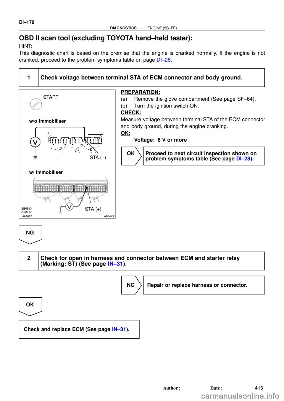
START
STA (+) w/o Immobiliser
w/ Immobiliser
STA (+)
DI±178
± DIAGNOSTICSENGINE (5S±FE)
413 Author�: Date�:
OBD II scan tool (excluding TOYOTA hand±held tester):
HINT:
This diagnostic chart is based on the premise that the engine is cranked normally. If the engine is not
cranked, proceed to the problem symptoms table on page DI±28.
1 Check voltage between terminal STA of ECM connector and body ground.
PREPARATION:
(a) Remove the glove compartment (See page SF±64).
(b) Turn the ignition switch ON.
CHECK:
Measure voltage between terminal STA of the ECM connector
and body ground, during the engine cranking.
OK:
Voltage: 6 V or more
OK Proceed to next circuit inspection shown on
problem symptoms table (See page DI±28).
NG
2 Check for open in harness and connector between ECM and starter relay
(Marking: ST) (See page IN±31).
NG Repair or replace harness or connector.
OK
Check and replace ECM (See page IN±31).
Page 2599 of 4770
A07554
ECM
+B 12
E7 B±Y J/C
B
J28 J27B
B±Y
Instrument
Panel J/B 22J 2K7
W±R EFI
Relay 1 3
52
2F4
W±B
2A 1
AM2
42L
B
FL
Block
MAIN
FL
B±GEngine
J/B No.2
5
1B
531K71W
IGN
1K
Room
W±R
IG
Switch
7 6
14
E9
BR
B±R
EC
E1
F6
F4EB
B±R
1
1
EFI
J23
J/C A
A
Battery
BR
(*2) (*1)
*1: w/ Immobiliser
*2: w/o ImmobiliserE924 (*2)
MREL 7
E10 B±Y (*1) 6II4 B±W (*1)
± DIAGNOSTICSENGINE (5S±FE)
DI±179
414 Author�: Date�:
ECM Power Source Circuit
CIRCUIT DESCRIPTION
When the ignition switch is turned ON, battery positive voltage is applied to the coil, closing the contacts of
the EFI main relay (Marking: EFI) and supplying power to terminal +B of the ECM.
WIRING DIAGRAM
DI01L±05
Page 2600 of 4770
BE6653
A03028
A03709
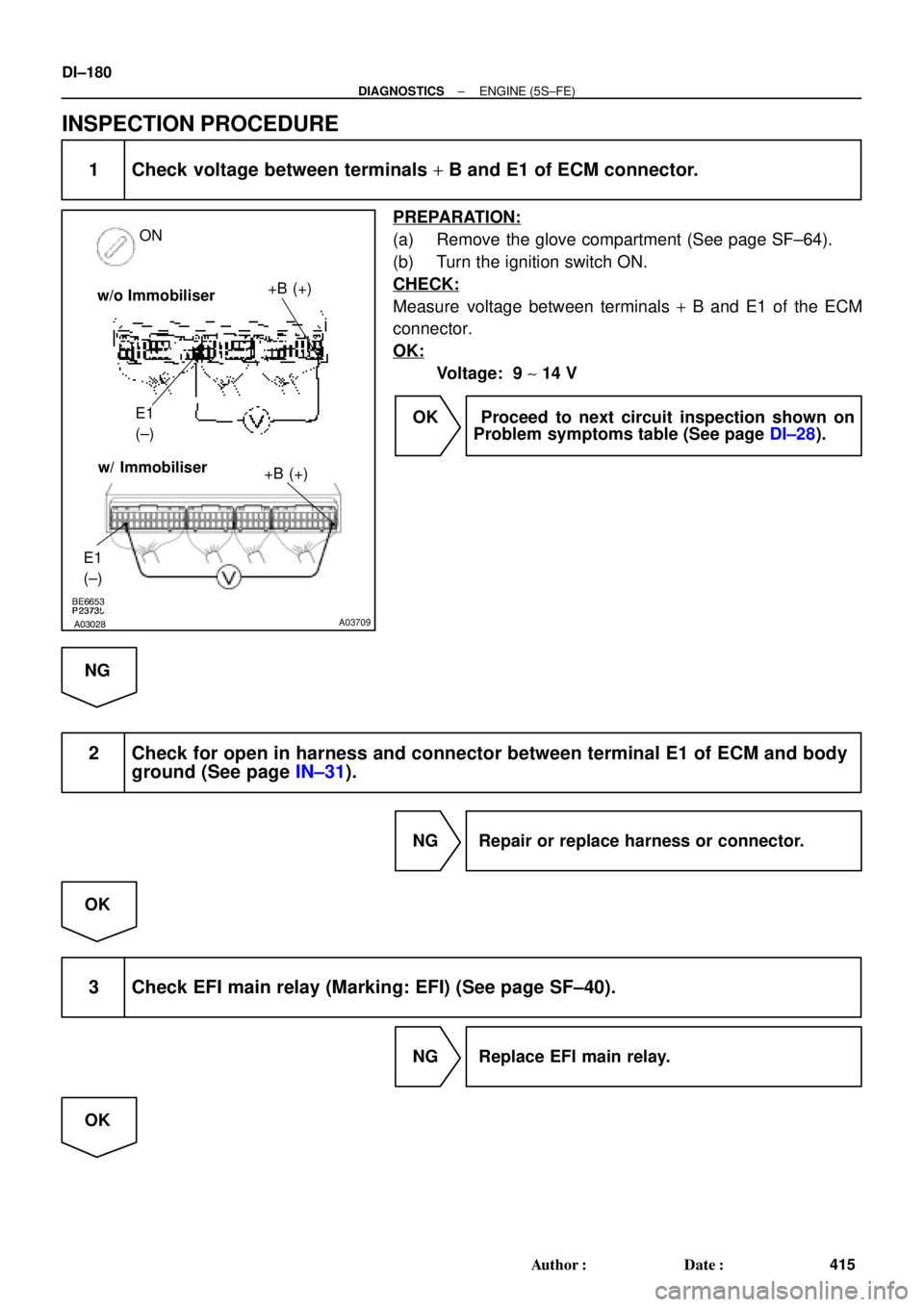
ON
+B (+)
E1
(±)
E1
(±)
+B (+)w/ Immobiliser w/o Immobiliser
DI±180
± DIAGNOSTICSENGINE (5S±FE)
415 Author�: Date�:
INSPECTION PROCEDURE
1 Check voltage between terminals + B and E1 of ECM connector.
PREPARATION:
(a) Remove the glove compartment (See page SF±64).
(b) Turn the ignition switch ON.
CHECK:
Measure voltage between terminals + B and E1 of the ECM
connector.
OK:
Voltage: 9 ~ 14 V
OK Proceed to next circuit inspection shown on
Problem symptoms table (See page DI±28).
NG
2 Check for open in harness and connector between terminal E1 of ECM and body
ground (See page IN±31).
NG Repair or replace harness or connector.
OK
3 Check EFI main relay (Marking: EFI) (See page SF±40).
NG Replace EFI main relay.
OK
Page 2601 of 4770
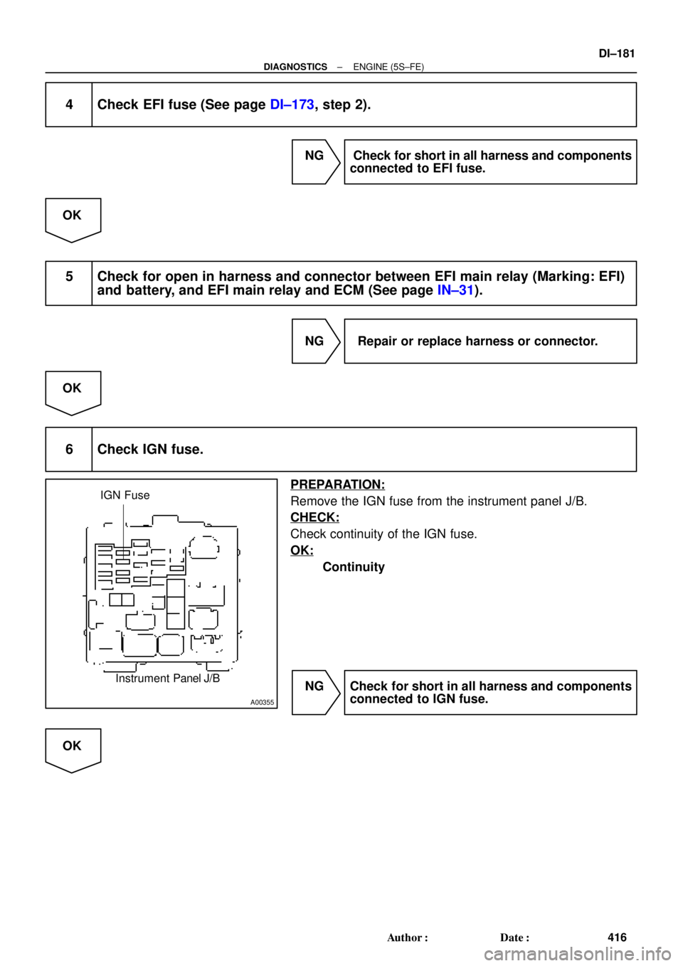
A00355
IGN Fuse
Instrument Panel J/B
± DIAGNOSTICSENGINE (5S±FE)
DI±181
416 Author�: Date�:
4 Check EFI fuse (See page DI±173, step 2).
NG Check for short in all harness and components
connected to EFI fuse.
OK
5 Check for open in harness and connector between EFI main relay (Marking: EFI)
and battery, and EFI main relay and ECM (See page IN±31).
NG Repair or replace harness or connector.
OK
6 Check IGN fuse.
PREPARATION:
Remove the IGN fuse from the instrument panel J/B.
CHECK:
Check continuity of the IGN fuse.
OK:
Continuity
NG Check for short in all harness and components
connected to IGN fuse.
OK