Page 2162 of 4770
 Close (c) Open
A12 Type C:
N20567
A12 Type C: BE±68
± BODY ELECTRICALPOWER WINDOW CONTROL SYSTEM
2288 Author�: MH Date�: 3/7/02
(d) Turn the ignition switch ON and check")
N20565
A3 Type B:
N20566
(b) Close (c) Open
A12 Type C:
N20567
A12 Type C: BE±68
± BODY ELECTRICALPOWER WINDOW CONTROL SYSTEM
2288 Author�: MH Date�: 3/7/02
(d) Turn the ignition switch ON and check that the meter
needle indicates battery positive voltage again.
If operation is not as specified, replace the relay.
15. Key±off power window signal:
INSPECT INTEGRATION RELAY (TYPE C) OPERA-
TION
HINT:
When the relay circuit is as specified, inspect the key±off power
window signal.
(a) Connect the positive (+) lead from the voltmeter to termi-
nal A12 and the negative (±) lead to body ground.
(b) Close the door with ignition switch turned to LOCK or
ACC, and check that the meter needle indicates battery
positive voltage.
(c) Open the door and check that the meter needle indicates
0 V.
(d) Turn the ignition switch ON and check that the meter
needle indicates battery positive voltage again.
If operation is not as specified, replace the relay.
16. INSPECT INTEGRATION RELAY CIRCUIT
(See page XX±XXX)
Page 2163 of 4770
BE0AP±02
Z19053
Instrument Panel J/B No.1
� POWER M±Fuse
� CIG Fuse
� DOOR Fuse
� Integration Relay
Power Window Master Switch
� Door Lock Control SwitchDoor Key Lock and Unlock Switch
Door Lock Assembly
� Door Lock Motor
� Door Unlock Detection Switch
Door Lock Assembly
� Door Lock Motor
� Door Unlock Detection Switch
Door Lock Control Switch
± BODY ELECTRICALPOWER DOOR LOCK CONTROL SYSTEM
BE±69
2289 Author�: Date�:
POWER DOOR LOCK CONTROL SYSTEM
LOCATION
Page 2166 of 4770

N20574
Type B:
Lock
A25
A12
N20575
Type B:
Unlock
A25A12
N20576
Type C:
Lock
A7
A6
N20577
Type C:
Unlock
A7 A6 BE±72
± BODY ELECTRICALPOWER DOOR LOCK CONTROL SYSTEM
2292 Author�: Date�:
9. Door lock signal:
INSPECT INTEGRATION RELAY (Type B) OPERATION
HINT:
When the relay circuit is as specified, inspect the door lock sig-
nal.
(a) Connect the positive (+) lead from the voltmeter to termi-
nal A12 and the negative (±) lead to terminal A25.
(b) Set the door lock control switch to UNLOCK and check
that the voltage rises from 0 V to battery positive voltage
for approximately 0.2 seconds.
(c) Reverse the polarity of the voltmeter leads.
(d) Set the door lock control switch to LOCK and check that
the voltage rises from 0 V to battery positive voltage for
approximately 0.2 seconds.
If operation is not as specified, replace the relay.
10. Door lock signal:
INSPECT INTEGRATION RELAY (Type C) OPERATION
HINT:
When the relay circuit is as specified, inspect the door lock sig-
nal.
(a) Connect the positive (+) lead from the voltmeter to termi-
nal A6 and the negative (±) lead to terminal A7.
(b) Set the door lock control switch to UNLOCK and check
that the voltage rises from 0 V to battery positive voltage
for approximately 0.2 seconds.
(c) Reverse the polarity of the voltmeter leads.
(d) Set the door lock control switch to LOCK and check that
the voltage rises from 0 V to battery positive voltage for
approximately 0.2 seconds.
If operation is not as specified, replace the relay.
11. INSPECT INTEGRATION RELAY CIRCUIT
(See page BE±14)
Page 2167 of 4770
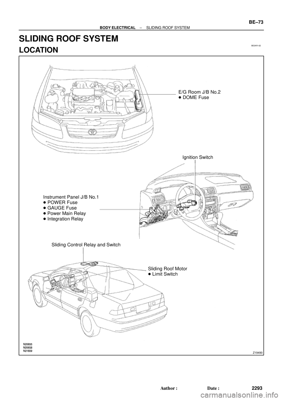
BE0AR±02
Z19490
E/G Room J/B No.2
� DOME Fuse
Ignition Switch
Instrument Panel J/B No.1
� POWER Fuse
� GAUGE Fuse
� Power Main Relay
� Integration Relay
Sliding Control Relay and Switch
Sliding Roof Motor
� Limit Switch
± BODY ELECTRICALSLIDING ROOF SYSTEM
BE±73
2293 Author�: Date�:
SLIDING ROOF SYSTEM
LOCATION
Page 2168 of 4770

BE0AS±02
N21643
Wire harness side:
12 3
4567 8
s±8±1
BE±74
± BODY ELECTRICALSLIDING ROOF SYSTEM
2294 Author�: Date�:
INSPECTION
1. INSPECT SLIDING ROOF CONTROL RELAY AND
SWITCH CIRCUIT
Disconnect the connector from the relay and switch and inspect
the connector on the wire harness side, as shown in the table.
TMMK made:
Tester connectionConditionSpecified condition
1 ± 5ConstantContinuity
2 ± GroundConstantContinuity
3 ± GroundLimit switch No.1 is OFF (Sliding roof is in a
closed position)No continuity
3 ± GroundLimit switch No.1 is ON (Sliding roof is in an open
position)Continuity
7 ± GroundLimit switch No.2 is OFF (Sliding roof is in a tilt
up position)No continuity
7 ± GroundLimit switch No.2 is ON (Sliding roof is in the
open position)Continuity
8 ± GroundLimit switch No.3 is OFF (Sliding roof is in a
closed position)No continuity
8 ± GroundLimit switch No.3 is ON (Sliding roof is in an open
position)Continuity
4 ± GroundIgnition switch is in a LOCK or ACC position* No voltage
4 ± GroundIgnition switch is in an ON positionBattery positive voltage
TMC made:
Tester connectionConditionSpecified condition
1 ± 5ConstantContinuity
2 ± GroundConstantContinuity
3 ± GroundNo.1 limit switch OFF (Sliding roof closed)No continuity
3 ± GroundNo.1 limit switch ON (Sliding roof opened)Continuity
7 ± GroundNo.2 limit switch OFF (Sliding roof tilted up open
approx. 200 mm (7.87 in.)No continuity
7 ± GroundNo.2 limit switch ON (Except for conditions
mentioned above)Continuity
4 ± GroundIgnition switch LOCK or ACC* No voltage
4 ± GroundIgnition switch ONBattery positive voltage
*: Exceptions: For 60 seconds after the ignition switch is turned
ON to OFF (ACC) or until driver or passenger door is opened
after the ignition switch is turned ON to OFF (ACC).
If the circuit is not as specified, replace the relay and switch.
Page 2170 of 4770

N21645
within 60
seconds
N21872
No.3
Limit Switch
No.1
Limit Switch
No.2
Limit Switch ON
OFF
N21180
No.1
Limit Switch
No.2
Limit Switch ON
OFF1
2
3 4
5
6 BE±76
± BODY ELECTRICALSLIDING ROOF SYSTEM
2296 Author�: Date�:
(b) With the sliding roof in fully opened position, hold the slid-
ing roof switch in ºTILT UPº position and check that the
sliding roof begins to close within 60 seconds.
If operation is not as specified, replace the motor.
4. TMMK made:
INSPECT SLIDING ROOF LIMIT SWITCH CIRCUIT
Switch positionTester connectionSpecified condition
No.1 limit switch OFF
(SW pin released)3 ± 5No continuity
No.1 limit switch ON
(SW pin pushed in)3 ± 5Continuity
No.2 limit switch OFF
(SW pin released)3 ± 6No continuity
No.2 limit switch ON
(SW pin pushed in)3 ± 6Continuity
No.3 limit switch OFF
(SW pin released)3 ± 4No continuity
No.3 limit switch ON
(SW pin pushed in)3 ± 4Continuity
5. TMC made:
INSPECT SLIDING ROOF LIMIT SWITCH CIRCUIT
Switch positionTester connectionSpecified condition
No.1 limit switch OFF
(SW pin released)4 ± 5No continuity
No.1 limit switch ON
(SW pin pushed in)4 ± 5Continuity
No.2 limit switch OFF
(SW pin released)4 ± 6No continuity
No.2 limit switch ON
(SW pin pushed in)4 ± 6Continuity
If continuity is not as specified, replace the switch.
6. INSPECT KEY±OFF SLIDING ROOF OPERATION
(See integration relay circuit on page BE±14)
Page 2272 of 4770
 Sub±Wire Harness G (SST)
ABSSub±Wire Harness L (SST)
Sub±Wire Harness I (SST) ActuatorABS Actuator Checker BR±50
± BRAKEABS ACTUATOR (DENSO Made)
2073 Author�: Date�")
BR0BD±02
W03244
R09422
(SST) Sub±Wire Harness G (SST)
ABSSub±Wire Harness L (SST)
Sub±Wire Harness I (SST) ActuatorABS Actuator Checker BR±50
± BRAKEABS ACTUATOR (DENSO Made)
2073 Author�: Date�:
ABS ACTUATOR (DENSO Made)
ON±VEHICLE INSPECTION
HINT:
Using the ABS actuator checker (SST), check the operation of
the actuator. If the actuator does not operate, check the opera-
tion of sub±wire harness G according to the instructions on
pages DI±502 and DI±507. If the solenoid and/or pump motor
relay are abnormal, replace the relay and inspect the actuator
operation again.
1. INSPECT BATTERY POSITIVE VOLTAGE
Battery positive voltage: 10 ± 14 V
2. DISCONNECT CONNECTORS
Disconnect the 2 connectors from the actuator.
3. CONNECT ACTUATOR CHECKER (SST)
(a) Connect the actuator checker (SST) to the actuator side
wire harness via the sub±wire harness (SST), as shown.
SST 09990±00150, 09990±00250, 09990±00300,
09990±00360
(b) Connect the red cable of the checker to the battery posi-
tive (+) terminal and black cable to the negative (±) termi-
nal. Connect the black cable of the sub±wire harness to
the battery negative (±) terminal or body ground.
Page 2283 of 4770

FR TRC
Connector
White
Connector
Sub ± Wire harness P (SST)
*: Connect the white connector with
the labeled (FF TRC) connector.(SST)
FF TRC
Con")
BR07A±06
W03246
W03897
Sub ± Wire Harness G (SST)
FR TRC
Connector
White
Connector
Sub ± Wire harness P (SST)
*: Connect the white connector with
the labeled (FF TRC) connector.(SST)
FF TRC
Connector Sub ± Wire
harness L
(SST)
ABS & TRAC
ActuatorABS Actuator Checker
± BRAKEABS & TRAC ACTUATOR
BR±61
2084 Author�: Date�:
ABS & TRAC ACTUATOR
ON±VEHICLE INSPECTION
HINT:
Using the ABS actuator checker (SST), check the operation of
the actuator. If the actuator does not operate, check the opera-
tion of sub±wire harness G according to the instructions on
pages DI±584 and DI±587. If the solenoid and/or pump motor
relay are abnormal, replace the relay and inspect the actuator
operation again.
1. INSPECT BATTERY POSITIVE VOLTAGE
Battery positive voltage: 10 ± 14 V
2. DISCONNECT CONNECTORS
Disconnect the 2 connectors from the actuator.
3. CONNECT ABS ACTUATOR CHECKER (SST)
(a) Connect the actuator checker (SST) to the actuator side
wire harness via the sub±wire harness (SST), as shown.
SST 09990±00150, 09990±00250, 09990±00360,
09990±00450
(b) Connect the red cable of the checker to the battery posi-
tive (+) terminal and black cable to the negative (±) termi-
nal. Connect the black cable of the sub±wire harness to
the battery negative (±) terminal or body ground.