Page 2109 of 4770
 Connect the negative (±) lea")
N20128
101
6
5
N20129
10
1 6
5
N20130
101 65
N20131
101 65
N20132
101 6
5
± BODY ELECTRICALIGNITION SWITCH AND KEY UNLOCK WARNING
SWITCHBE±15
2235 Author�: Date�:
(f) Connect the negative (±) lead from the battery to terminal
6.
(g) Disconnect the negative (±) lead from the battery to termi-
nal 5.
(h) Check that the buzzerr stops sounding.
If operation is not as specified, replace the relay.
4. Key unlock warning system:
INSPECT INTEGRATION RELAY (TYPE B) OPERA-
TION
(a) Connect the positive (+) lead from the battery to terminal
1.
(b) Connect the negative (±) lead from the battery to termi-
nals 5, 6 and 10.
(c) Check the buzzerr sounds.
(d) Disconnect the negative (±) lead from the battery to termi-
nal 6.
(e) Check that the buzzerr stops sounding.
(f) Connect the negative (±) lead from the battery to terminal
6.
(g) Disconnect the negative (±) lead from the battery to termi-
nal 5.
(h) Check that the buzzerr stops sounding.
If operation is not as specified, replace the relay.
5. Key unlock warning system:
INSPECT INTEGRATION RELAY (TYPE C) OPERA-
TION
(a) Connect the positive (+) lead from the battery to terminal
1.
(b) Connect the negative (±) lead from the battery to termi-
nals 5, 6 and 10.
(c) Check the buzzerr sounds.
Page 2110 of 4770
 Disconnect the negat")
N20133
101 65
N20134
101 65
N20135
Junction block side:
1 2 3 4 5 6 7 8 10 11 9 12
BE±16± BODY ELECTRICALIGNITION SWITCH AND KEY UNLOCK WARNING
SWITCH
2236 Author�: Date�:
(d) Disconnect the negative (±) lead from the battery to termi-
nal 6.
(e) Check that the buzzerr stops sounding.
(f) Connect the negative (±) lead from the battery to terminal
6.
(g) Disconnect the negative (±) lead from the battery to termi-
nal 5.
(h) Check that the buzzerr stops sounding.
If operation is not as specified, replace the relay.
6. INSPECT INTEGRATION RELAY (TYPE A) CIRCUIT
(a) Remove the relay from the junction block No.1 and in-
spect the connector on the junction block side.
Tester connectionConditionSpecified condition
2 ± Ground
4 ± GroundPassenger's door courtesy switch OFF (Door
closed)No continuity
2 ± Ground
4 ± GroundPassenger's door courtesy switch ON (Door
opened)Continuity
5 ± GroundKey unlock warning switch OFFNo continuity
5 ± GroundKey unlock warning switch ONContinuity
6 ± GroundDriver's door courtesy switch OFFNo continuity
6 ± GroundDriver's door courtesy switch ONContinuity
8 ± GroundBuckle switch OFF (Seat belt unfastened)No continuity
8 ± GroundBuckle switch ON (Seat belt fastened)Continuity
10 ± GroundConstantContinuity
1 ± GroundConstantBattery positive voltage
7 ± Ground
9 ± GroundIgnition switch LOCK or ACCNo voltage
7 ± Ground
9 ± GroundIgnition switch ONBattery positive voltage
Page 2111 of 4770
 Disconnect the co")
N20136
Wire harness side:
1234
N20135
Junction block side:
1 2 3 4 5 6 7 8
10 119
12
± BODY ELECTRICALIGNITION SWITCH AND KEY UNLOCK WARNING
SWITCHBE±17
2237 Author�: Date�:
(b) Disconnect the connector from the integration relay and
inspect the connector on the wire harness side.
Tester connectionConditionSpecified condition
1 ± GroundLight control switch OFFNo continuity
1 ± GroundLight control switch HEAD or TAILContinuity
4 ± GroundLight control switch OFF or TAILNo continuity
4 ± GroundLight control switch HEADContinuity
2 ± Ground
3 ± GroundConstantBattery positive voltage
If the circuit is as specified, try replacing the relay with a new
one.
If the circuit is not as specified, inspect the circuits connected
to other parts.
7. INSPECT INTEGRATION RELAY (TYPE B) CIRCUIT
(a) Remove the relay from the junction block No.1 and in-
spect the connector on the junction block side.
Tester connectionConditionSpecified condition
2 ± GroundAll door courtesy switches OFF (Except Driver's
Door/ Door closed)No continuity
2 ± GroundOne of the door courtesy switches ON (Except
Driver's Door/ Door opened)Continuity
4 ± GroundDoor courtesy switches except that of the driver's
door OFF (Door closed)No continuity
4 ± GroundOne of the door courtesy switches except that of
the driver's door ON (Door opened)Continuity
Page 2112 of 4770

N20137
Wire harness side:
Wire harness side:
20 14 13 1211 10 8 479
22 21 19 18 17 15 1656 123
23 24 25
1234
Connector ºAº
Connector ºBº
eh±25±1
h±4±1
BE±18± BODY ELECTRICALIGNITION SWITCH AND KEY UNLOCK WARNING
SWITCH
2238 Author�: Date�:
5 ± GroundKey unlock warning switch OFFNo continuity
5 ± GroundKey unlock warning switch ONContinuity
6 ± GroundDriver's door courtesy switch OFF (Door closed)No continuity
6 ± GroundDriver's door courtesy switch ON (Door opened)Continuity
8 ± GroundBuckle switch OFF (Seat belt unfastened)No continuity
8 ± GroundBuckle switch ON (Seat belt fastened)Continuity
10 ± GroundConstantContinuity
1 ± GroundConstantBattery positive voltage
7 ± Ground
9 ± GroundIgnition switch LOCK or ACCNo voltage
7 ± Ground
9 ± GroundIgnition switch ONBattery positive voltage
11 ± GroundIgnition switch LOCKNo voltage
11 ± GroundIgnition switch ACC or ONBattery positive voltage
(b) Disconnect the connector from the integration relay and
inspect the connectors on the wire harness side.
Tester connectionConditionSpecified condition
A3 ± GroundConstantContinuity
A5 ± GroundDriver's door unlock detection switch OFF (Door
locked)No continuity
A5 ± GroundDriver's door unlock detection switch ON (Door
unlocked)Continuity
A6 ± GroundPassenger's door courtesy switch OFF (Door
closed)No continuity
Page 2113 of 4770

N20135
Junction block side:
1 2 3 4 5 6 7 8
10 119
12
± BODY ELECTRICALIGNITION SWITCH AND KEY UNLOCK WARNING
SWITCHBE±19
2239 Author�: Date�:
A6 ± GroundPassenger's door courtesy switch ON (Door
opened)Continuity
A7 ± GroundPassenger's door unlock detection switch OFF
(Door locked)No continuity
A7 ± GroundPassenger's door unlock detection switch ON
(Door unlocked)Continuity
A9 ± GroundRear door unlock detection switch OFF (Door
locked)No continuity
A9 ± GroundRear door unlock detection switch ON (Door
unlocked)Continuity
A11 ± A12
A12 ± A25ConstantContinuity
A16 ± GroundDoor lock manual switch OFF or UNLOCKNo continuity
A16 ± GroundDoor lock manual switch LOCKContinuity
A17 ± GroundDoor lock manual switch OFF or LOCKNo continuity
A17 ± GroundDoor lock manual switch UNLOCKContinuity
A18 ± GroundDriver's and passenger's door key lock and
unlock switch OFF or UNLOCKNo continuity
A18 ± GroundDriver's or passenger's door key lock and unlock
switch LOCKContinuity
A19 ± GroundDriver's door key lock and unlock switch OFF or
LOCKNo continuity
A19 ± GroundDriver's door key lock and unlock switch
UNLOCKContinuity
A20 ± GroundPassenger's door key lock and unlock switch
OFF or LOCKNo continuity
A20 ± GroundPassenger's door key lock and unlock switch
UNLOCKContinuity
A1 ± GroundConstantBattery positive voltage
B1 ± GroundLight control switch OFFNo voltage
B1 ± GroundLight control switch TAIL or HEADBattery positive voltage
B4 ± GroundLight control switch OFF or TAILNo voltage
B4 ± GroundLight control switch HEADBattery positive voltage
B2 ± Ground
B3 ± GroundConstantBattery positive voltage
If the circuit is as specified, try replacing the relay with a new
one.
If the circuit is not as specified, inspect the circuits connected
to other parts.
8. INSPECT INTEGRATION RELAY (TYPE C) CIRCUIT
(a) Remove the relay from the junction block No.1 and in-
spect the connector on the junction block side.
Page 2114 of 4770

N20138
Wire harness side:
Wire harness side:
13 12 11 10 84
795
6 123
1234
Connector ºAº
Connector ºBº BE±20
± BODY ELECTRICALIGNITION SWITCH AND KEY UNLOCK WARNING
SWITCH
2240 Author�: Date�:
Tester connectionConditionSpecified condition
2 ± GroundAll door courtesy switches OFF (Except Driver's
Door/ Door closed)No continuity
2 ± GroundOne of the door courtesy switches ON (Except
Driver's Door/ Door opened)Continuity
4 ± GroundDoor courtesy switches except that of the driver's
door OFF (Door closed)No continuity
4 ± GroundOne of the door courtesy switches except that of
the driver's door ON (Door opened)Continuity
5 ± GroundKey unlock warning switch OFFNo continuity
5 ± GroundKey unlock warning switch ONContinuity
6 ± GroundDriver's door courtesy switch OFF (Door closed)No continuity
6 ± GroundDriver's door courtesy switch ON (Door opened)Continuity
8 ± GroundBuckle switch OFF (Seat belt unfastened)No continuity
8 ± GroundBuckle switch ON (Seat belt fastened)Continuity
10 ± GroundConstantContinuity
1 ± GroundConstantBattery positive voltage
7 ± Ground
9 ± GroundIgnition switch LOCK or ACCNo voltage
7 ± Ground
9 ± GroundIgnition switch ONBattery positive voltage
11 ± GroundIgnition switch LOCKNo voltage
11 ± GroundIgnition switch ACC or ONBattery positive voltage
(b) Disconnect the connector from the integration relay and
inspect the connectors on the wire harness side.
Page 2115 of 4770

± BODY ELECTRICALIGNITION SWITCH AND KEY UNLOCK WARNING
SWITCHBE±21
2241 Author�: Date�:
Tester connectionConditionSpecified condition
A1 ± GroundDoor lock manual switch OFF or UNLOCKNo continuity
A1 ± GroundDoor lock manual switch LOCKContinuity
A2 ± GroundDoor lock manual switch OFF or LOCKNo continuity
A2 ± GroundDoor lock manual switch UNLOCKContinuity
A3 ± GroundDriver's and passenger's door key lock and
unlock switch OFF or UNLOCKNo continuity
A3 ± GroundDriver's or passenger's door key lock and unlock
switch LOCKContinuity
A4 ± GroundDriver's door key lock and unlock switch OFF or
LOCKNo continuity
A4 ± GroundDriver's door key lock and unlock switch
UNLOCKContinuity
A5 ± GroundPassenger's door key lock and unlock switch
OFF or LOCKNo continuity
A5 ± GroundPassenger's door key lock and unlock switch
UNLOCKContinuity
A6 ± A7ConstantContinuity
A8 ± GroundPassenger's door courtesy switch OFF (Door
closed)No continuity
A8 ± GroundPassenger's door courtesy switch ON (Door
opened)Continuity
A9 ± GroundDriver's door unlock detection switch OFF (Door
closed)No continuity
A9 ± GroundDriver's door unlock detection switch ON (Door
opened)Continuity
A10 ± GroundPassenger's door unlock detection switch OFF
(Door closed)No continuity
A10 ± GroundPassenger's door unlock detection switch ON
(Door opened)Continuity
A11 ± GroundRear door unlock detection switch OFF (Door
closed)No continuity
A11 ± GroundRear door unlock detection switch ON (Door
opened)Continuity
A12 ± GroundConstantContinuity
A13 ± GroundConstantBattery positive voltage
B1 ± GroundLight control switch OFFNo voltage
B1 ± GroundLight control switch TAIL or HEADBattery positive voltage
B4 ± GroundLight control switch OFF or TAILNo voltage
B4 ± GroundLight control switch HEADBattery positive voltage
B2 ± Ground
B3 ± GroundConstantBattery positive voltage
If the circuit is as specified, try replacing the relay with a new
one.
If the circuit is not as specified, inspect the circuits connected
to other parts.
Page 2116 of 4770
BE0A4±02
I08436
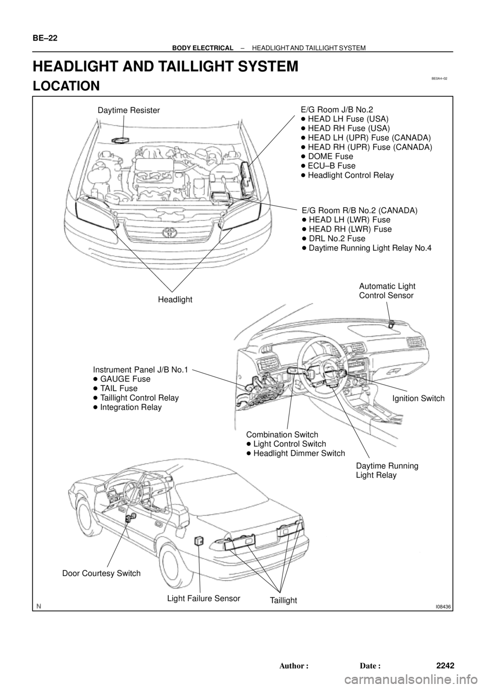
Daytime ResisterE/G Room J/B No.2
� HEAD LH Fuse (USA)
� HEAD RH Fuse (USA)
� HEAD LH (UPR) Fuse (CANADA)
� HEAD RH (UPR) Fuse (CANADA)
� DOME Fuse
� ECU±B Fuse
� Headlight Control Relay
E/G Room R/B No.2 (CANADA)
� HEAD LH (LWR) Fuse
� HEAD RH (LWR) Fuse
� DRL No.2 Fuse
� Daytime Running Light Relay No.4
Headlight
Instrument Panel J/B No.1
� GAUGE Fuse
� TAIL Fuse
� Taillight Control Relay
� Integration Relay
Daytime Running
Light RelayIgnition Switch
Combination Switch
� Light Control Switch
� Headlight Dimmer Switch
Door Courtesy Switch
Light Failure Sensor
Taillight
Automatic Light
Control Sensor
BE±22
± BODY ELECTRICALHEADLIGHT AND TAILLIGHT SYSTEM
2242 Author�: Date�:
HEADLIGHT AND TAILLIGHT SYSTEM
LOCATION