Page 1535 of 4770
AC0LL±02
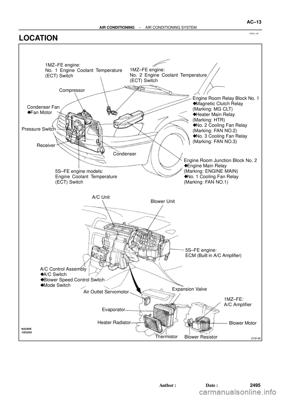
Z19146
1MZ±FE engine:
No. 1 Engine Coolant Temperature
(ECT) Switch
Compressor
Engine Room Junction Block No. 2
� Engine Main Relay
(Marking: ENGINE MAIN)
� No. 1 Cooling Fan Relay
(Marking: FAN NO.1)Engine Room Relay Block No. 1
� Magnetic Clutch Relay
(Marking: MG CLT)
� Heater Main Relay
(Marking: HTR)
� No. 2 Cooling Fan Relay
(Marking: FAN NO.2)
� No. 3 Cooling Fan Relay
(Marking: FAN NO.3)
5S±FE engine models:
Engine Coolant Temperature
(ECT) Switch Receiver Pressure SwitchCondenser Fan
� Fan Motor1MZ±FE engine:
No. 2 Engine Coolant Temperature
(ECT) Switch
Condenser
Blower Unit A/C Unit
A/C Control Assembly
� A/C Switch
� Blower Speed Control Switch
� Mode Switch
Air Outlet Servomotor
Heater Radiator
Thermistor
Blower ResistorBlower Motor 1MZ±FE:
A/C Amplifier Expansion Valve5S±FE engine:
ECM (Built in A/C Amplifier)
Evaporator
± AIR CONDITIONINGAIR CONDITIONING SYSTEM
AC±13
2495 Author�: Date�:
LOCATION
Page 1536 of 4770

AC21T±01
AC±14
± AIR CONDITIONINGTROUBLESHOOTING
2496 Author�: Date�:
TROUBLESHOOTING
PROBLEM SYMPTOMS TABLE
Use the table below to help you find the cause of the problem. The numbers indicate the priority of the likely
cause of the problem. Check each part in order. If necessary, replace these parts.
SymptomSuspect AreaSee page
No blower operation
4. HTR Fuse
5. Heater main relay
6. Blower motor
7. Blower resistor
8. Blower speed control switch
9. Wire harness±
AC±70
AC±63
AC±64
AC±84
±
No air temperature control1. Engine coolant volume
2. A/C control assembly±
AC±80
No air inlet control1. A/C control assemblyAC±80
No air outlet control
1. HTR Fuse
2. Air outlet servomotor
3. Mode switch±
AC±65
AC±84
No compressor operation
1. Refrigerant volume
2. A.C Fuse
3. HTR Fuse
4. Magnetic clutch relay
5. Magnetic clutch
6. Compressor
7. Pressure switch
8. Heater main relay
9. Blower speed control switch
10.A/C switch
11. *1 ECM
*
2 A/C amplifier
12.Wire harness
AC±3
±
±
AC±71
AC±39
AC±39
AC±67
AC±70
AC±84
AC±84
DI±218
AC±88
±
No compressor operates intermittently
1. Refrigerant volume
2. Condenser fan
3. Pressure switch
4. *1 ECM
*2 A/C amplifier
5. Thermistor
6. Wire harnessAC±3
AC±74
AC±67
DI±218
AC±88
AC±24
±
No cool air comes out
1. Refrigerant volume
2. Refrigerant pressure
3. Drive belt
4. Compressor lock sensor
5. Magnetic clutch
6. Compressor
7. Pressure switch
8. Thermistor
9. A/C switch
10.*1 ECM
*2 A/C amplifier
11. Wire harnessAC±3
AC±3
AC±16
AC±16
AC±39
AC±39
AC±67
AC±24
AC±84
DI±218
AC±88
±
Page 1537 of 4770

± AIR CONDITIONINGTROUBLESHOOTING
AC±15
2497 Author�: Date�:
Cool air comes out only at high engine rpm
1. Refrigerant volume
2. Drive belt
3. Magnetic clutch
4. Compressor
5. Condenser
6. Condenser fan
7. Receiver
8. Expansion valve
9. Evaporator
10.Thermistor
11. Refrigerant line
12.Pressure switch
13.*
1 ECM
*2 A/C amplifier
AC±3
AC±16
AC±16
AC±39
AC±52
AC±74
AC±49
AC±59
AC±30
AC±24
AC±21
AC±67
DI±218
AC±88
No engine idle±up when A/C switch ON
1. *1 ECM
*2 A/C amplifier
2. Wire harness
DI±218
AC±88
±
Blinking of A/C indicator
1. *1 ECM
*2 A/C amplifier
2. Thermistor
3. Compressor
DI±218
AC±88
AC±24
AC±39
A/C indicator does not lights up when turn mode switch to DEF.
position
1. A/C Fuse
2. Mode switch
3. A/C switch
4. *
1 ECM
*2 A/C amplifier
5. Wire harness
±
AC±84
AC±84
DI±218
AC±88
±
No warm air comes out
1. Engine coolant volume
2. A/C control assembly
3. Heater radiator±
AC±80
AC±57
No condenser fan operation
1. CDS FAN Fuse
2. Engine main relay
3. Cooling fan relay No. 1
4. Cooling fan relay No. 2
5. Cooling fan relay No. 3
6. Condenser fan motor
7. Pressure switch
8. *
1 Engine coolant temp. switch
*2 No. 1 Engine coolant temp. switch
9. *2No. 2 Engine coolant temp. switch
10.Wire harness
±
±
AC±72
AC±72
AC±72
AC±74
AC±67
AC±92
AC±92
AC±92
±
*1: 5S±FE Engine Models
*
2: 1MZ±FE Engine Models
Page 1592 of 4770
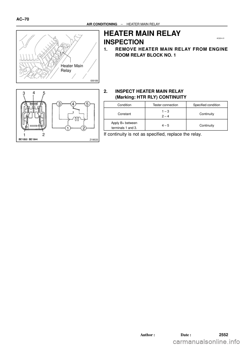
I09189
Heater Main
Relay
AC224±01
Z19533
34
5
1212 34 5 AC±70
± AIR CONDITIONINGHEATER MAIN RELAY
2552 Author�: Date�:
HEATER MAIN RELAY
INSPECTION
1. REMOVE HEATER MAIN RELAY FROM ENGINE
ROOM RELAY BLOCK NO. 1
2. INSPECT HEATER MAIN RELAY
(Marking: HTR RLY) CONTINUITY
ConditionTester connectionSpecified condition
Constant1 ± 3
2 ± 4Continuity
Apply B+ between
terminals 1 and 3.4 ± 5Continuity
If continuity is not as specified, replace the relay.
Page 1593 of 4770
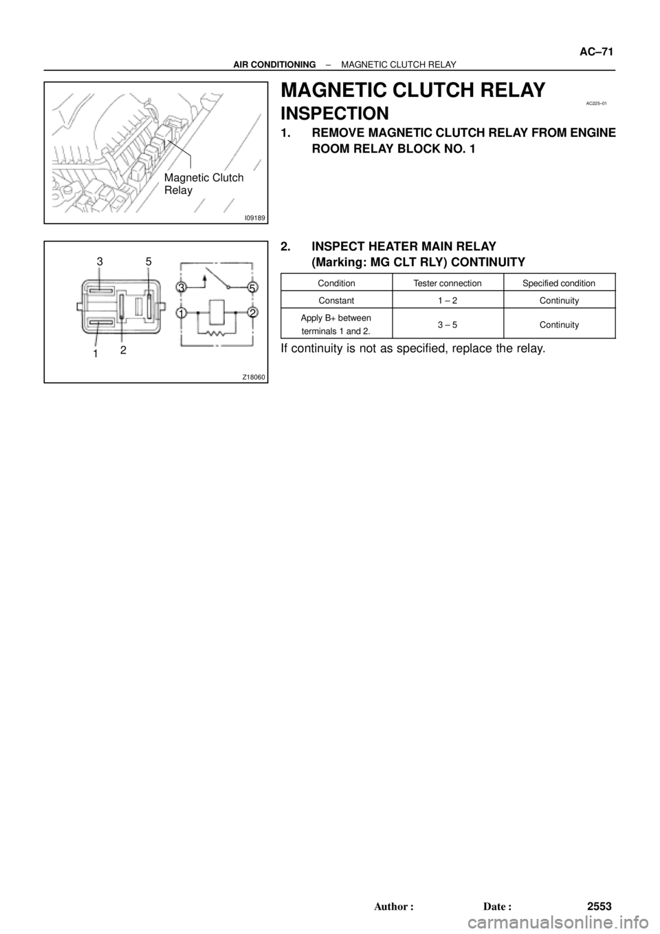
I09189
Magnetic Clutch
Relay
AC225±01
Z18060
35
1212 3
5
± AIR CONDITIONINGMAGNETIC CLUTCH RELAY
AC±71
2553 Author�: Date�:
MAGNETIC CLUTCH RELAY
INSPECTION
1. REMOVE MAGNETIC CLUTCH RELAY FROM ENGINE
ROOM RELAY BLOCK NO. 1
2. INSPECT HEATER MAIN RELAY
(Marking: MG CLT RLY) CONTINUITY
ConditionTester connectionSpecified condition
Constant1 ± 2Continuity
Apply B+ between
terminals 1 and 2.3 ± 5Continuity
If continuity is not as specified, replace the relay.
Page 1594 of 4770
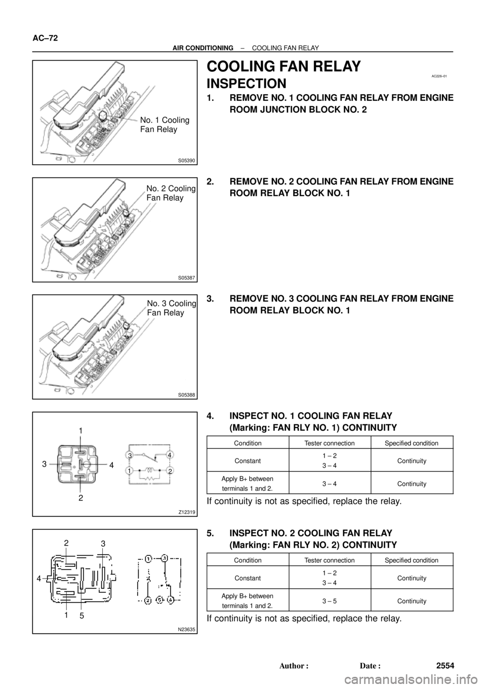
S05390
No. 1 Cooling
Fan Relay
AC226±01
S05387
No. 2 Cooling
Fan Relay
S05388
No. 3 Cooling
Fan Relay
Z12319
1
3
24
1
2 34
N23635
5 1 42
3 AC±72
± AIR CONDITIONINGCOOLING FAN RELAY
2554 Author�: Date�:
COOLING FAN RELAY
INSPECTION
1. REMOVE NO. 1 COOLING FAN RELAY FROM ENGINE
ROOM JUNCTION BLOCK NO. 2
2. REMOVE NO. 2 COOLING FAN RELAY FROM ENGINE
ROOM RELAY BLOCK NO. 1
3. REMOVE NO. 3 COOLING FAN RELAY FROM ENGINE
ROOM RELAY BLOCK NO. 1
4. INSPECT NO. 1 COOLING FAN RELAY
(Marking: FAN RLY NO. 1) CONTINUITY
ConditionTester connectionSpecified condition
Constant1 ± 2
3 ± 4Continuity
Apply B+ between
terminals 1 and 2.3 ± 4Continuity
If continuity is not as specified, replace the relay.
5. INSPECT NO. 2 COOLING FAN RELAY
(Marking: FAN RLY NO. 2) CONTINUITY
ConditionTester connectionSpecified condition
Constant1 ± 2
3 ± 4Continuity
Apply B+ between
terminals 1 and 2.3 ± 5Continuity
If continuity is not as specified, replace the relay.
Page 1595 of 4770
Z18060
12 3
5
12 3
5
± AIR CONDITIONINGCOOLING FAN RELAY
AC±73
2555 Author�: Date�:
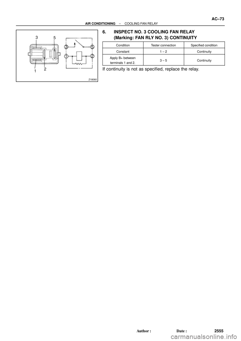
6. INSPECT NO. 3 COOLING FAN RELAY
(Marking: FAN RLY NO. 3) CONTINUITY
ConditionTester connectionSpecified condition
Constant1 ± 2Continuity
Apply B+ between
terminals 1 and 2.3 ± 5Continuity
If continuity is not as specified, replace the relay.
Page 1596 of 4770

AC0N6±02
N20290
21
A AC±74
± AIR CONDITIONINGCONDENSER FAN
2556 Author�: Date�:
CONDENSER FAN
ON±VEHICLE INSPECTION
1. INSPECT CONDENSER FAN OPERATION
Inspect the fan operation, as shown in the chart below.
Test conditions:
�Ignition switch ON
�Blower speed control switch position ºHIº
�A/C switch ON
ConditionFan operation (Fan speed)
Engine coolant temperature
83°C (181°F) or belowNot rotate
Engine coolant temperature
98°C (208°F) or aboveRotate
Refrigerant pressure is less than
1,520 kPa (15.5 kgf/cm2, 220 psi)Not rotate (Low Speed)
Refrigerant pressure is 1,520 kPa
(15.5 kgf/cm2, 220 psi) or aboveRotate (High Speed)
If operation is not as specified, proceed next inspection.
2. INSPECT CONDENSER FAN MOTOR OPERATION
(a) Disconnect the fan connector.
(b) Connect the battery and ammeter to the connector, as
shown in the illustation.
(c) Check that the fan rotates smoothly, and then check that
the reading on the ammeter.
Specified amperage: 10.1 ± 1.8 A at 20 °C (68 °F)
�If operation is not as specified, replace the fan mo-
tor.
�If operation is as specified, check the pressure
switch, cooling fan relays and engine coolant temp.
switch.