Page 2146 of 4770

N20217
OFF
ONOhmmeter
Z05732
Warning Light
Ignition
Switch
Battery
1
BE0044
Warning Light
Ignition
Switch
Battery
Z16167
1
2 OFF
ON
N02354
1
2OFF
ON BE±52
± BODY ELECTRICALCOMBINATION METER
2272 Author�: Date�:
18. INSPECT WASHER FLUID LEVEL WARNING SWITCH
(a) Check that no continuity exists between terminals with the
switch OFF (float up).
(b) Check that continuity exists between terminals with the
switch ON (float down).
If operation is not as specified, replace the switch.
19. INSPECT OPEN DOOR WARNING LIGHT
Disconnect the connector from the door courtesy switch and
ground terminal 1 on the wire harness side, and check that the
warning light lights up.
If the warning light does not light up, inspect the bulb or wire har-
ness.
20. INSPECT SEAT BELT WARNING LIGHT
(a) Remove the integration relay from the instrument panel
junction block.
(b) Ground terminal 2 on the integration relay with the con-
nectors still connected.
(c) Turn the ignition switch ON and check that the warning
light lights up.
If the warning light does not light up, inspect the bulb or wire har-
ness.
21. w/o Power seat:
INSPECT BUCKLE SWITCH CONTINUITY
(a) Check that continuity exists between the terminals on the
switch side connector with the switch ON (belt fastened).
(b) Check that no continuity exists between the terminals on
the switch side connector with the switch OFF (belt unfas-
tened).
If operation is not as specified, replace the seat belt inner belt.
22. w/ Power seat:
INSPECT BUCKLE SWITCH CONTINUITY
(a) Check that continuity exists between terminals 1 and 2 on
the switch side connector with the switch ON (belt fas-
tened).
(b) Check that no continuity exists between terminals 1 and
2 on the switch side connector with the switch OFF (belt
unfastened).
If operation is not as specified, replace the seat belt inner belt.
Page 2147 of 4770
N20219
Type A:
Type B and C:1
7
9
10
1
7
910
N20220
Type A:
Type B and C:1
7
9
10
1
7910 88
± BODY ELECTRICALCOMBINATION METER
BE±53
2273 Author�: Date�:
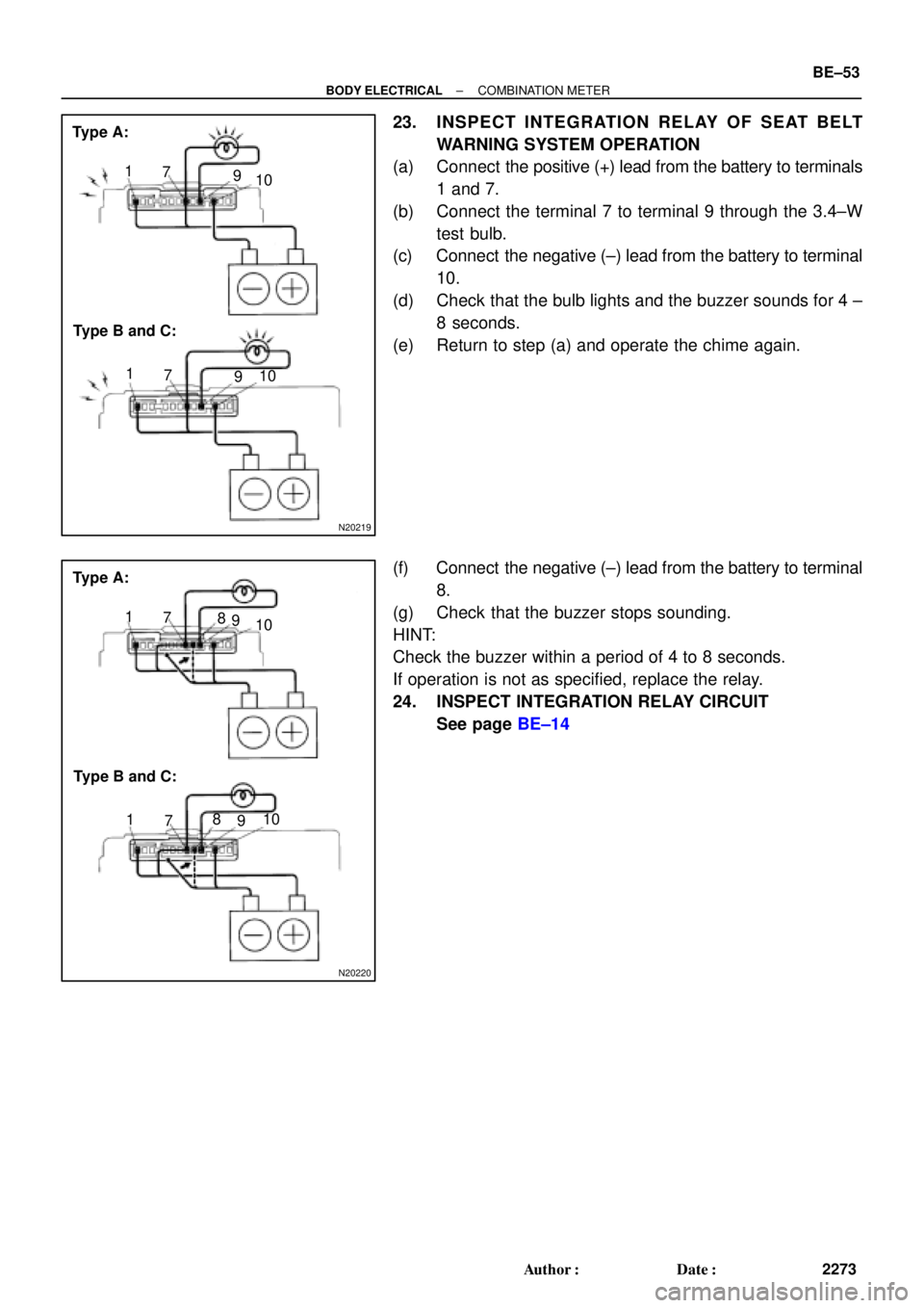
23. INSPECT INTEGRATION RELAY OF SEAT BELT
WARNING SYSTEM OPERATION
(a) Connect the positive (+) lead from the battery to terminals
1 and 7.
(b) Connect the terminal 7 to terminal 9 through the 3.4±W
test bulb.
(c) Connect the negative (±) lead from the battery to terminal
10.
(d) Check that the bulb lights and the buzzer sounds for 4 ±
8 seconds.
(e) Return to step (a) and operate the chime again.
(f) Connect the negative (±) lead from the battery to terminal
8.
(g) Check that the buzzer stops sounding.
HINT:
Check the buzzer within a period of 4 to 8 seconds.
If operation is not as specified, replace the relay.
24. INSPECT INTEGRATION RELAY CIRCUIT
See page BE±14
Page 2148 of 4770
N08958
270°
32
1
Z09972
(a)(b)
AB
CAB
C BE±54
± BODY ELECTRICALCOMBINATION METER
2274 Author�: Date�:
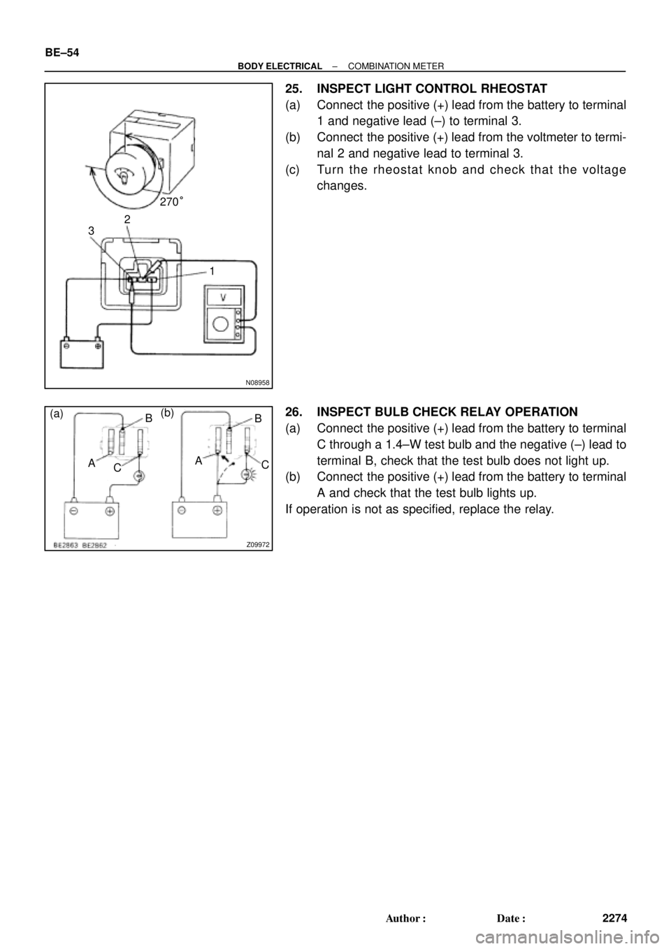
25. INSPECT LIGHT CONTROL RHEOSTAT
(a) Connect the positive (+) lead from the battery to terminal
1 and negative lead (±) to terminal 3.
(b) Connect the positive (+) lead from the voltmeter to termi-
nal 2 and negative lead to terminal 3.
(c) Turn the rheostat knob and check that the voltage
changes.
26. INSPECT BULB CHECK RELAY OPERATION
(a) Connect the positive (+) lead from the battery to terminal
C through a 1.4±W test bulb and the negative (±) lead to
terminal B, check that the test bulb does not light up.
(b) Connect the positive (+) lead from the battery to terminal
A and check that the test bulb lights up.
If operation is not as specified, replace the relay.
Page 2149 of 4770
BE0AL±03
Z19051
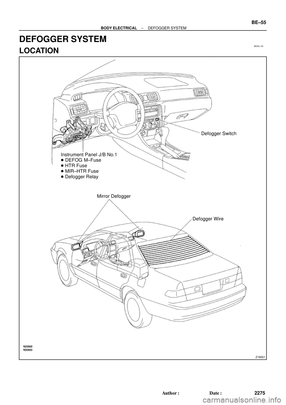
Defogger Switch
Instrument Panel J/B No.1
� DEFOG M±Fuse
� HTR Fuse
� MIR±HTR Fuse
� Defogger Relay
Mirror Defogger
Defogger Wire
± BODY ELECTRICALDEFOGGER SYSTEM
BE±55
2275 Author�: Date�:
DEFOGGER SYSTEM
LOCATION
Page 2150 of 4770

BE0AM±03
N20315
Switch side:
1 2
3
4 5 6
N20314
ON3 4 5
Z08467
1
2
3456 Wire harness side:
S±6±1
N14863
1
2 35 12
35 BE±56
± BODY ELECTRICALDEFOGGER SYSTEM
2276 Author�: Date�:
INSPECTION
1. INSPECT DEFOGGER SWITCH CONTINUITY
Check that is continuity exists between terminals 2 and 6.
If continuity is not as specified, check the bulb.
2. INSPECT DEFOGGER TIMER OPERATION
(a) Connect the positive (+) lead from the battery to terminal
4 and the negative (±) lead to terminal 3.
(b) Connect the positive (+) lead from the battery to terminal
5 through a 3.4±W tester bulb.
(c) Push the defogger switch ON, check that the indicator
light and test bulb light up for 12 to 18 minutes, then the
indicator light and test bulb light goes out.
If operation is not as specified, replace the switch.
3. INSPECT DEFOGGER TIMER CIRCUIT
Disconnect the connector from the switch and inspect the con-
nector on the wire harness side, as shown in the table.
Tester connectionConditionSpecified condition
3 ± GroundConstantContinuity
4 ± GroundIgnition switch LOCK or ACCNo voltage
4 ± GroundIgnition switch ONBattery positive voltage
5 ± GroundIgnition switch LOCK or ACCNo voltage
5 ± GroundIgnition switch ONBattery positive voltage
±Connect terminals 3 and 5.Defogger system operation is normal
If the circuit is not as specified, replace the switch.
4. INSPECT DEFOGGER RELAY CONTINUITY
ConditionTester connectionSpecified condition
Constant1 ± 2Continuity
Apply B+ between
terminals 1 and 2.3 ± 5Continuity
If continuity is not as specified, replace the relay.
Page 2153 of 4770
BE0AN±03
Z19052
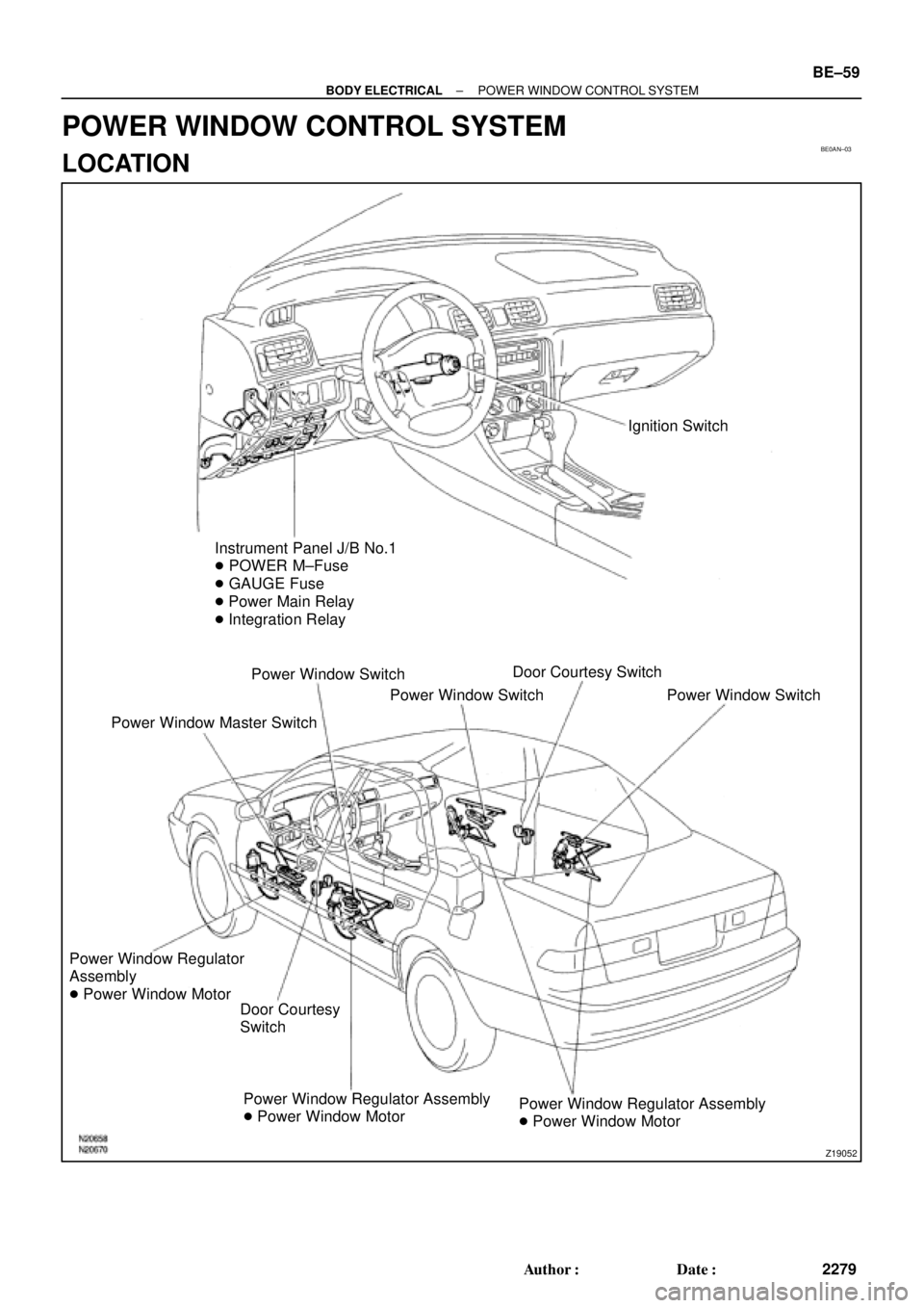
Ignition Switch
Instrument Panel J/B No.1
� POWER M±Fuse
� GAUGE Fuse
� Power Main Relay
� Integration Relay
Power Window Switch
Power Window Master SwitchPower Window SwitchDoor Courtesy Switch
Power Window Switch
Power Window Regulator
Assembly
� Power Window Motor
Door Courtesy
Switch
Power Window Regulator Assembly
� Power Window MotorPower Window Regulator Assembly
� Power Window Motor
± BODY ELECTRICALPOWER WINDOW CONTROL SYSTEM
BE±59
2279 Author�: Date�:
POWER WINDOW CONTROL SYSTEM
LOCATION
Page 2157 of 4770

Z05742
123 456
7 8 9 10 11 121314 Wire harness side:
e±14±1±A
N20560
1 2 3 4 5
N20561
1 2 3 4 5
N14863
1235 12
35
± BODY ELECTRICALPOWER WINDOW CONTROL SYSTEM
BE±63
2283 Author�: Date�:
5. INSPECT POWER WINDOW MASTER SWITCH CIR-
CUIT
Disconnect the connector from the master switch and inspect
the connector on the wire harness side, as shown in the follow-
ing page.
Tester connectionConditionSpecified condition
4 ± GroundConstantContinuity
8 ± GroundIgnition switch position LOCK or ACC*No voltage
8 ± GroundIgnition switch position ONBattery positive voltage
*Exceptions: During 60 seconds after the ignition switch is
turned ON to OFF (ACC) or until driver or a passenger's door
is opened after the ignition switch is turned ON to OFF (ACC).
If the circuit is not as specified, inspect the circuits connected
to other parts.
6. Front passenger's door:
INSPECT POWER WINDOW SWITCH CONTINUITY
Switch positionTester connectionSpecified condition
UP1 ± 2, 3 ± 4Continuity
OFF1 ± 2, 3 ± 5Continuity
DOWN1 ± 4, 3 ± 5Continuity
If continuity is not as specified, replace the switch.
7. Rear door:
INSPECT POWER WINDOW SWITCH CONTINUITY
Switch positionTester connectionSpecified condition
UP1 ± 3, 4 ± 5Continuity
OFF1 ± 2, 4 ± 5Continuity
DOWN1 ± 2, 3 ± 5Continuity
If continuity is not as specified, replace the switch.
8. INSPECT POWER MAIN RELAY CONTINUITY
ConditionTester connectionSpecified condition
Constant1 ± 2Continuity
Apply B+ between
terminals 1 and 2.3 ± 5Continuity
If continuity is not as specified, replace the relay.
Page 2161 of 4770
 Close(c) Open
A3 Type B:
± BODY ELECTRICALPOWER WINDOW CONTROL SYSTEM
BE±67
2287 Author�: Date�:
(f) Approximately 60 seconds later, connect the positive")
I21313
2
1
I12561
2
1
I12560
21
N20564
(b) Close(c) Open
A3 Type B:
± BODY ELECTRICALPOWER WINDOW CONTROL SYSTEM
BE±67
2287 Author�: Date�:
(f) Approximately 60 seconds later, connect the positive (+)
lead from the battery to terminal 1 and the negative (±)
lead to terminal 2, and check that the window begins to
descend.
If operation is not as specified, replace the motor.
13. Rear Door:
INSPECT POWER WINDOW MOTOR PTC THERM-
ISTOR OPERATION
(a) Disconnect the connector from the power window switch.
(b) Connect the positive (+) lead from the ammeter to termi-
nal 1 on the wire harness side connector and the negative
(±) lead to negative terminal of the battery.
(c) Connect the positive (+) lead from the battery to terminal
2 on the wire harness side connector, and raise the win-
dow to the fully position.
(d) Continue to apply voltage and check that the current
changes to less than 1 A within 4 to 90 seconds.
(e) Disconnect the leads from the terminals.
(f) Approximately 60 seconds later, connect the positive (+)
lead from the battery to terminal 2 and the negative (±)
lead to terminal 1, and check that the window begins to
descend.
If operation is not as specified, replace the motor.
14. Key±off power window signal:
INSPECT INTEGRATION RELAY (TYPE B) OPERA-
TION
HINT:
When the relay circuit is as specified, inspect the key±off power
window signal.
(a) Connect the positive (+) lead from the voltmeter to termi-
nal A3 and the negative (±) lead to body ground.
(b) Close the door with ignition switch turned to LOCK or
ACC, and check that the meter needle indicates battery
positive voltage.
(c) Open the door and check that the meter needle indicates
0 V.