Page 2526 of 4770
A07551
ECM
J19
J/C
7 From
Battery
B
213
EFI Relay VSV
for EGR
21P-B23
E9EGR
E01
2K2
2J EFI
II4
Engine Room J/B No.2 1B
B-W 9
B-Y
B
2AB-Y
II3
EB
W-B
2F4
6
B-W B-YE815
MREL E107 (*1) (*2)
(*2)
*1: w/o Immobiliser
*2: w/ Immobiliser(*2) (*2)
5B-Y
(*1)From
Ignition SW DI±106
± DIAGNOSTICSENGINE (5S±FE)
341 Author�: Date�:
WIRING DIAGRAM
Page 2543 of 4770

A07552
3
2
1Y
P
BRECM
1
1
7
9
22 J19
J/C
8
E8
E8
EBE8
E01 E9
E8
EJ/C
J28
J27
10
1V
6
2F From
BatteryB±Y VSV
for EVAP
2V±W
VSV for Vapor
Pressure
Sensor
9
Engine Room J/B No.2 B±Y
EFI II3
53
B±Y
VC
PTNK
E2
EVP
TPC5 V
E1
E01
2J 2A
2K
2
*1: w/o Immobiliser
*2: w/ Immobiliser
(*1) (*2)
MREL(*2)
E8
8
E9
3
E8
16
E10
7 Y Y Vapor Pressure Sensor
P P
BR BR
E
ID1 ID1
1
V V
B±Y
B±W B±W
II4 II4
5
ID1
ID1
ID1
6 5
237
8
II4 II4
II2
(*1) (*2)(*1) (*2)
W±B
B±Y12
BB
B±Y
12
7 4
EFI Relay J27 J27B±Y
B
BJ/C
(*2) (*2)
B±R(*1)From
Ignition SW
± DIAGNOSTICSENGINE (5S±FE)
DI±123
358 Author�: Date�:
WIRING DIAGRAM
INSPECTION PROCEDURE
HINT:
�If DTC P0441 (Evaporative Emission Control System Incorrect Purge Flow), P0446 (Evaporative
Emission Control System Vent Control Malfunction), P0450 (Evaporative Emission Control System
Pressure Sensor Malfunction) or P0451 is output after DTC P0440 (Evaporative Emission Control Sys-
tem Malfunction), first troubleshoot DTC P0441, P0446, P0450 or P0451. If no malfunction is detected,
troubleshoot DTC P0440 next.
�Ask the customer whether, after the MIL came on, the customer found the fuel tank cap loose and tight-
ened it. Also ask the customer whether the fuel tank cap was loose when refuelling. If the fuel tank cap
was not loose, it was the cause of the DTC. If the fuel tank cap was not loose or if the customer was
not sure if it was loose, troubleshoot according to the following procedure.
�Read freeze frame data using TOYOTA hand±held tester or OBD II scan tool. Because freeze frame
records the engine conditions when the malfunction is detected, when troubleshooting it is useful for
determining whether the vehicle was running or stopped, the engine warmed up or not, the air±fuel
ratio lean or rich, etc. at the time of the malfunction.
�When the ENGINE RUN TIME in the freeze frame data is less than 200 seconds, carefully check the
VSV for EVAP, charcoal canister and vapor pressure sensor.
Page 2553 of 4770
± DIAGNOSTICSENGINE (5S±FE)
DI±133
368 Author�: Date�:
7 Check vacuum hose between intake manifold and VSV for EVAP, and VSV for
EVAP and charcoal canister.
CHECK:
(a) Check that the vacuum hose is connected correctly.
(b) Check the vacuum hose for looseness and disconnection.
(c) Check the vacuum hose for cracks, hole, damage and blockage.
NG Repair or replace.
OK
8 Check operation of VSV for EVAP (See page SF±45).
OK Go to step 9.
NG
Replace VSV, charcoal canister and then clean the vacuum hose between throttle body and VSV
for EVAP, and VSV for EVAP and charcoal canister.
9 Check for open and short in harness and connector between EFI main relay
(Marking: EFI) and VSV for EVAP, and VSV for EVAP and ECM
(See page IN±31).
NG Repair or replace harness or connector.
OK
Check and replace ECM (See page IN±31).
Page 2555 of 4770

E2 (±)
E2 (±) w/o Immobiliser
w/ Immobiliser
PTNK (+)
Vapor Pressure Sensor
± DIAGNOSTICSENGINE (5S±FE)
DI±135
370 Author�: Date�:
12 Check for ope")
A03018
A03280
A03421
VSV Connector for
PTNK (+)
E2 (±)
E2 (±) w/o Immobiliser
w/ Immobiliser
PTNK (+)
Vapor Pressure Sensor
± DIAGNOSTICSENGINE (5S±FE)
DI±135
370 Author�: Date�:
12 Check for open and short in harness and connector between EFI main relay
(Marking: EFI) and VSV for vapor pressure sensor, and VSV for vapor pressure
sensor and ECM (See page IN±31).
NG Repair or replace harness or connector.
OK
Check and replace ECM (See page IN±31).
13 When VSV connector for vapor pressure sensor is disconnected and VSV for
EVAP is ON, measure voltage between terminals PTNK and E2 of ECM connector.
PREPARATION:
(a) Remove the glove compartment (See page SF±64).
(b) Connect the TOYOTA hand±held tester to the DLC3.
(c) Disconnect the VSV connector for the vapor pressure
sensor.
(d) Select the ACTIVE TEST mode on the TOYOTA hand±
held tester.
(e) Start the engine.
CHECK:
Measure voltage between terminals PTNK and E2 of the ECM
connector using the TOYOTA hand±held tester when the VSV
for the EVAP is ON.
OK:
Voltage: 2.0 V or less
OK Go to step 15.
NG
Page 2560 of 4770
A03020A03424
ON
OFF
ONTPC
E
G
FFE
G
VSV is ON
VSV is OFF OFFONTPC
w/o Immobiliser
w/ Immobiliser
DI±140
± DIAGNOSTICSENGINE (5S±FE)
375 Author�: Date�:
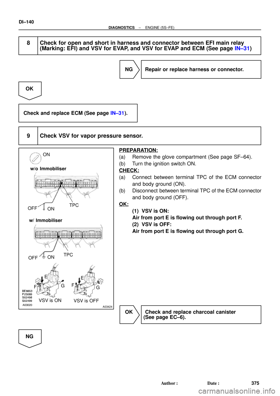
8 Check for open and short in harness and connector between EFI main relay
(Marking: EFI) and VSV for EVAP, and VSV for EVAP and ECM (See page IN±31)
NG Repair or replace harness or connector.
OK
Check and replace ECM (See page IN±31).
9 Check VSV for vapor pressure sensor.
PREPARATION:
(a) Remove the glove compartment (See page SF±64).
(b) Turn the ignition switch ON.
CHECK:
(a) Connect between terminal TPC of the ECM connector
and body ground (ON).
(b) Disconnect between terminal TPC of the ECM connector
and body ground (OFF).
OK:
(1) VSV is ON:
Air from port E is flowing out through port F.
(2) VSV is OFF:
Air from port E is flowing out through port G.
OK Check and replace charcoal canister
(See page EC±6).
NG
Page 2561 of 4770
± DIAGNOSTICSENGINE (5S±FE)
DI±141
376 Author�: Date�:
10 Check operation of VSV for vapor pressure sensor (See page SF±47).
NG Go to step 11.
OK
Replace VSV and clean vacuum hoses between charcoal canister and VSV for vapor pressure
sensor, and VSV for vapor pressure sensor and vapor pressure sensor, and then check the char-
coal canister.
11 Check for open and short in harness and connector between EFI main relay
(Marking: EFI) and VSV for vapor pressure sensor, and VSV for vapor pressure
sensor and ECM (See page IN±31).
NG Repair or replace harness or connector.
OK
Check and replace ECM (See page IN±31).
12 Check fuel tank over fill check valve (See page EC±6).
NG Replace fuel tank over fill check valve or fuel
tank.
OK
Check and replace charcoal canister
(See page EC±6).
Page 2568 of 4770

P01559
Throttle Valve
To Cylinder ECM Signal From
Air
Cleaner
Valve
IAC Valve
Intake Air
Chamber
A07553
B±Y 9
2B±Y B±Y
II3J19
J/CIAC ValveECM
1
3 2
B
EFI
5
1 Engine Room J/B No.2
42
2J
W±B
B
ISCO
E01
E01 ISCC10
9W
B±OE9
E9
1
2A
2K
EFI Relay
EB
From
BatteryB
*1: w/o Immobiliser
*2: w/ Immobiliser(*1) (*2)
E97
E96
(*2) (*1)
E107MREL2FB±W B±W
II4
(*2)
7
6(*2) (*2)
3
B±R
(*1)From
Ignition SW DI±148
± DIAGNOSTICSENGINE (5S±FE)
383 Author�: Date�:
DTC P0505 Idle Control System Malfunction
CIRCUIT DESCRIPTION
The rotary solenoid type IAC valve is located on the throttle
body and intake air bypassing the throttle valve is directed to
the IAC valve through a passage.
In this way the intake air volume bypassing the throttle valve is
regulated, controlling the engine speed.
The ECM operates only the IAC valve to perform idle±up and
provide feedback for the target idling speed.
DTC No.DTC Detecting ConditionTrouble AreaTrouble Area
P0505Idle speed continues to vary greatly from the target speed
(2 trip detection logic)
�IAC valve is stuck or closed
�Open or short in IAC valve circuit
�Open or short in A/C switch circuit
�Air intake (hose loose)
�ECM
WIRING DIAGRAM
DI01C±05
Page 2582 of 4770
DI±162
± DIAGNOSTICSENGINE (5S±FE)
397 Author�: Date�:
2 Check resistance of A/F sensor heater (See page SF±59).
NG Replace A/F sensor.
OK
Check and repair harness or connector between EFI main relay (Marking: EFI) and A/F sensor,
and A/F sensor and ECM (See page IN±31).
 (*2)
(*2)
*1: w")