Page 2411 of 4770
CO03U±03
B05943
B05944
± COOLING (1MZ±FE)ELECTRIC COOLING FAN
CO±29
1637 Author�: Date�:
REMOVAL
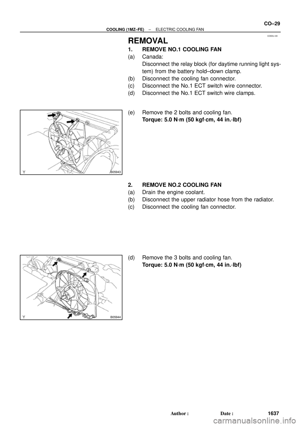
1. REMOVE NO.1 COOLING FAN
(a) Canada:
Disconnect the relay block (for daytime running light sys-
tem) from the battery hold±down clamp.
(b) Disconnect the cooling fan connector.
(c) Disconnect the No.1 ECT switch wire connector.
(d) Disconnect the No.1 ECT switch wire clamps.
(e) Remove the 2 bolts and cooling fan.
Torque: 5.0 N´m (50 kgf´cm, 44 in.´lbf)
2. REMOVE NO.2 COOLING FAN
(a) Drain the engine coolant.
(b) Disconnect the upper radiator hose from the radiator.
(c) Disconnect the cooling fan connector.
(d) Remove the 3 bolts and cooling fan.
Torque: 5.0 N´m (50 kgf´cm, 44 in.´lbf)
Page 2418 of 4770

S05391
Engine
Main Relay
CO03Z±03
S04974
Ohmmeter
1
Continuity OhmmeterOhmmeter Continuity
No
Continuity 2
5
43
S04973
Ohmmeter
1
Ohmmeter
Continuity No
Continuity
2
5
43
Battery CO±36
± COOLING (1MZ±FE)ENGINE MAIN RELAY
1644 Author�: Date�:
ENGINE MAIN RELAY
INSPECTION
1. REMOVE RELAY BOX COVER
2. REMOVE ENGINE MAIN RELAY
(Marking: ENGINE MAIN)
3. INSPECT RELAY CONTINUITY
(a) Using an ohmmeter, check that there is continuity be-
tween terminals 3 and 5.
If there is no continuity, replace the relay.
(b) Check that there is continuity between terminals 2 and 4.
If there is no continuity, replace the relay.
(c) Check that there is no continuity between terminals 1 and
2.
If there is continuity, replace the relay.
4. INSPECT RELAY OPERATION
(a) Apply battery positive voltage across terminals 3 and 5.
(b) Using an ohmmeter, check that there is no continuity be-
tween terminals 2 and 4.
If there is continuity, replace the relay.
(c) Check that there is continuity between terminals 1 and 2.
If there is no continuity, replace the relay.
5. REINSTALL ENGINE MAIN RELAY
6. REINSTALL RELAY BOX COVER
Page 2419 of 4770

S05390
No.1 Cooling
Fan Relay
CO040±03
S04975
Ohmmeter
ContinuityContinuity
Ohmmeter 1
3
24
S04976
Ohmmeter
No Continuity
1
3
24
Battery
S05387
No.2 Cooling
Fan Relay
S04972
Ohmmeter
Ohmmeter Ohmmeter
No Continuity 1
32 4
5
Continuity
± COOLING (1MZ±FE)COOLING FAN RELAY
CO±37
1645 Author�: Date�:
COOLING FAN RELAY
INSPECTION
1. REMOVE RELAY BOX COVER
2. INSPECT NO.1 COOLING FAN RELAY
(a) Remove the No.1 cooling fan relay. (Marking: FAN NO.1)
(b) Inspect the No.1 cooling fan relay continuity.
(1) Using an ohmmeter, check that there is continuity
between terminals 1 and 2.
If there is no continuity, replace the relay.
(2) Check that there is continuity between terminals 3
and 4.
If there is no continuity, replace the relay.
(c) Inspect the No.1 cooling fan relay operation.
(1) Apply battery positive voltage across terminals 1
and 2.
(2) Using an ohmmeter, check that there is no continu-
ity between terminals 3 and 4.
If there is continuity, replace the relay.
(d) Reinstall the No.1 cooling fan relay.
3. INSPECT NO.2 COOLING FAN RELAY
(a) Remove the No.2 cooling fan relay. (Marking: FAN NO.2)
(b) Inspect the No.2 cooling fan relay continuity.
(1) Using an ohmmeter, check that there is continuity
between terminals 1 and 2.
If there is no continuity, replace the relay.
(2) Check that there is continuity between terminals 3
and 4.
If there is no continuity, replace the relay.
(3) Check that there is no continuity between terminals
3 and 5.
If there is continuity, replace the relay.
Page 2420 of 4770

S04971
OhmmeterBattery
No ContinuityOhmmeter
Continuity 1
32 4
5
S05388
No.3 Cooling
Fan Relay
S04970
Ohmmeter
No ContinuityOhmmeter
1
32
5 Continuity
S04969
Ohmmeter
1
32
5
Continuity Battery CO±38
± COOLING (1MZ±FE)COOLING FAN RELAY
1646 Author�: Date�:
(c) Inspect the No.2 cooling fan relay operation.
(1) Apply battery positive voltage across terminals 1
and 2.
(2) Using an ohmmeter, check that there is no continu-
ity between terminals 3 and 4.
If there is continuity, replace the relay.
(d) Reinstall the No.2 cooling fan relay.
4. INSPECT NO.3 COOLING FAN RELAY
(a) Remove the No.3 cooling fan relay. (Marking: FAN NO.3)
(b) Inspect the No.3 cooling fan relay continuity.
(1) Using an ohmmeter, check that there is continuity
between terminals 1 and 2.
If there is mo continuity, replace the relay.
(2) Check that there is no continuity between terminals
3 and 5.
If there is continuity, replace the relay.
(c) Inspect the No.3 cooling fan relay operation.
(1) Apply battery positive voltage across terminals 1
and 2.
(2) Using an ohmmeter, check that there is continuity
between terminals 3 and 5.
If there is no continuity, replace the relay.
(d) Reinstall the No.3 cooling fan relay.
5. REINSTALL RELAY BOX COVER
Page 2448 of 4770

263 Author�: Date�:
PROBLEM SYMPTOMS TABLE
SymptomSuspect AreaSee page
Engine does not crank (Does not start)1. Starter
2. starter relayST±2
ST±20
No i")
DI00L±03
DI±28
± DIAGNOSTICSENGINE (5S±FE)
263 Author�: Date�:
PROBLEM SYMPTOMS TABLE
SymptomSuspect AreaSee page
Engine does not crank (Does not start)1. Starter
2. starter relayST±2
ST±20
No initial combustion (Does not start)
1. ECM power source circuit
2. Fuel pump control circuit
3. Engine control module (ECM)DI±179
DI±183
IN±31
No complete combustion (Does not start)1. Fuel pump control circuitDI±183
Engine cranks normally (Difficult to start)
1. Starter signal circuit
2. Fuel pump control circuit
3. CompressionDI±176
DI±183
EM±3
Cold engine (Difficult to start)1. Starter signal circuit
2. Fuel pump control circuitDI±176
DI±183
Hot engine (Difficult to start)1. Starter signal circuit
2. Fuel pump control circuitDI±176
DI±183
High engine idle speed (Poor idling)1. A/C switch circuit
2. ECM power source circuitAC±84
DI±179
Low engine idle speed (Poor idling)1. A/C switch circuit
2. Fuel pump control circuit AC±84
DI±183
Rough idling (Poor idling)1. Compression
2. Fuel pump control circuitEM±3
DI±183
Hunting (Poor idling)1. ECM power source circuit
2. Fuel pump control circuitDI±179
DI±183
Hesitation/Poor acceleration (Poor driveability)1. Fuel pump control circuit
2. A/T faulty DI±183
DI±405
Surging (Poor driveability)1. Fuel pump control circuitDI±183
Soon after starting (Engine stall)1. Fuel pump control circuitDI±183
During A/C operation (Engine stall)1. A/C switch circuit
2. Engine control module (ECM) AC±84
IN±31
A/C switch indicatior blinking1. A/C Compressor lock sensor circuit
2. A/C Evaporator temp. sensor circuitDI±190
DI±192
Unable to refuel/ Difficult to refuel1. ORVR systemEC±6
Page 2476 of 4770

A03597
B±Y
FL
Block47
EFI
IGN
14 2
4 EFI
Relay
21
53
B±Y
BR
3
12 B
B
1
24 3 9
II3
J/CB
W±R
P±B
W
BG
P±B 56
2
5
1K
14
HT2 21 O 1W
E9E8
E9 E8
MAIN FLE8 1B
B 1ECMAF�
OX2 HTAF
AF� 1K
2F
E03 E1E04 A/F
Sensor
Engine Room R/B No.2
B±YJ19 J/C
2
1
II2II3
II3
EB
Heated
Oxygen
Sensor
(Bank 1
Sensor 2)
EC
Instrument
Panel J/B7
3 5
6
7
2L 2A
F611
F4
B±G
Battery B±R
2K
2J
W±B
3.3V
3.0V
AM2 B
W±R
J27
*1: w/o Immobiliser
*2: w/ Immobiliser
(*1)
(*2)
to Analog±Digital
Converter
E914 E8 13
(*1) (*2) J27
B±Y
B±Y
IG Switch
B±R
*3: California
(*6) (*3) (*6) (*3)
(*1)
2
MREL
E107
(*2)
EE
J27 J27
J/C
B BB±Y
II4
6
B±W(*2)
B±W(*2)
*5:TMC Made
*6:TMMK Made
L(*5)
(*3)
B±W(*5)
(*3)
BR
*4: Except California
DI±56
± DIAGNOSTICSENGINE (5S±FE)
291 Author�: Date�:
HINT:
�After confirming DTC P0125, use the OBD II scan tool or TOYOTA hand-held tester to confirm voltage
output of A/F sensor from the CURRENT DATA.
�The ECM controls the voltage of AF� and AF� terminals of ECM to the fixed voltage. Therefore, it
is impossible to confirm the A/F sensor output voltage without OBD II scan tool or TOYOTA hand±held
tester.
�OBD II scan tool (excluding TOYOTA hand±held tester) displays the one fifth of the A/F sensor output
voltage which is displayed on the TOYOTA hand±held tester.
WIRING DIAGRAM
INSPECTION PROCEDURE
HINT:
�If the vehicle run out fuel, the air±fuel ratio is LEAN and DTC P0125 will be recorded.
The MIL then comes on.
�Read freeze frame data using TOYOTA hand±held tester or OBD II scan tool. Because freeze frame
records the engine conditions when the malfunction is detected, when troubleshooting it is useful for
determining whether the vehicle was running or stopped, the engine warmed up or not, the air±fuel
ratio lean or rich, etc. at the time of the malfunction.
Page 2482 of 4770

A03596
B±Y
Engine Room R/B No.2
Battery
IG Switch17
EFI
W±R7 7 2
5 EFI
Relay
5 3
24
W±BP±B
BR14 2314 2
3
9
II3
B±Y
B±Y
W±R B
W B±Y
B
BR6
128
25 1 2K
21 1KE8
E9
AM2
E8
E9ECM
OX1
OX2 HT1
HT2 1K 2JB±Y
J/C
1B
2F5 B±R
1W
Heated
Oxygen
Sensor
(Bank 1
Sensor 1)
II2
II3Heated
Oxygen
Sensor
(Bank 1
Sensor 2)E03
B J19 J/C
BBB
3
MAIN 2A 2L 4
F4 F6FL
Block
B±GP±B
J27 J27
1
EB
EC
6
IGN
E03 L±YE1
E1 Instrument
Panel J/B
11
B±R
*1: w/o Immobiliser
*2: w/ Immobiliser
(*2) (*1)
E9 14E8 E9 E85
1
13
(*2) (*1)(*1) (*2)(*1) (*2) (*3)
EB±Y
(*3) (*3)
(*1)FL
*3: Except California BII3
E
B±YJ27 J27
MREL
E10 B±W
II4
6
B±W(*2)
(*3)
7(*2)(*2)
BR BR
DI±62
± DIAGNOSTICSENGINE (5S±FE)
297 Author�: Date�:
HINT:
After confirming DTC P0125, use the OBD II scan tool or TOYOTA hand-held tester to confirm voltage output
of the heated oxygen sensor (bank 1 sensor 1) from the CURRENT DATA.
If voltage output of the heated oxygen sensor (bank 1 sensor 1) is 0 V, heated oxygen sensor (bank 1 sensor
1) circuit may be open or short.
WIRING DIAGRAM
INSPECTION PROCEDURE
HINT:
�If the vehicle run out fuel, the air±fuel ratio is LEAN and DTC P0125 will be recorded.
The MIL then comes on.
�Read freeze frame data using TOYOTA hand±held tester or OBD II scan tool. Because freeze frame
records the engine conditions when the malfunction is detected, when troubleshooting it is useful for
determining whether the vehicle was running or stopped, the engine warmed up or not, the air±fuel
ratio lean or rich, etc. at the time of the malfunction.
Page 2496 of 4770
A03014A03415
ON
HT1
HT2
w/o Immobiliser
w/ Immobiliser
HT1
HT2
DI±76
± DIAGNOSTICSENGINE (5S±FE)
311 Author�: Date�:
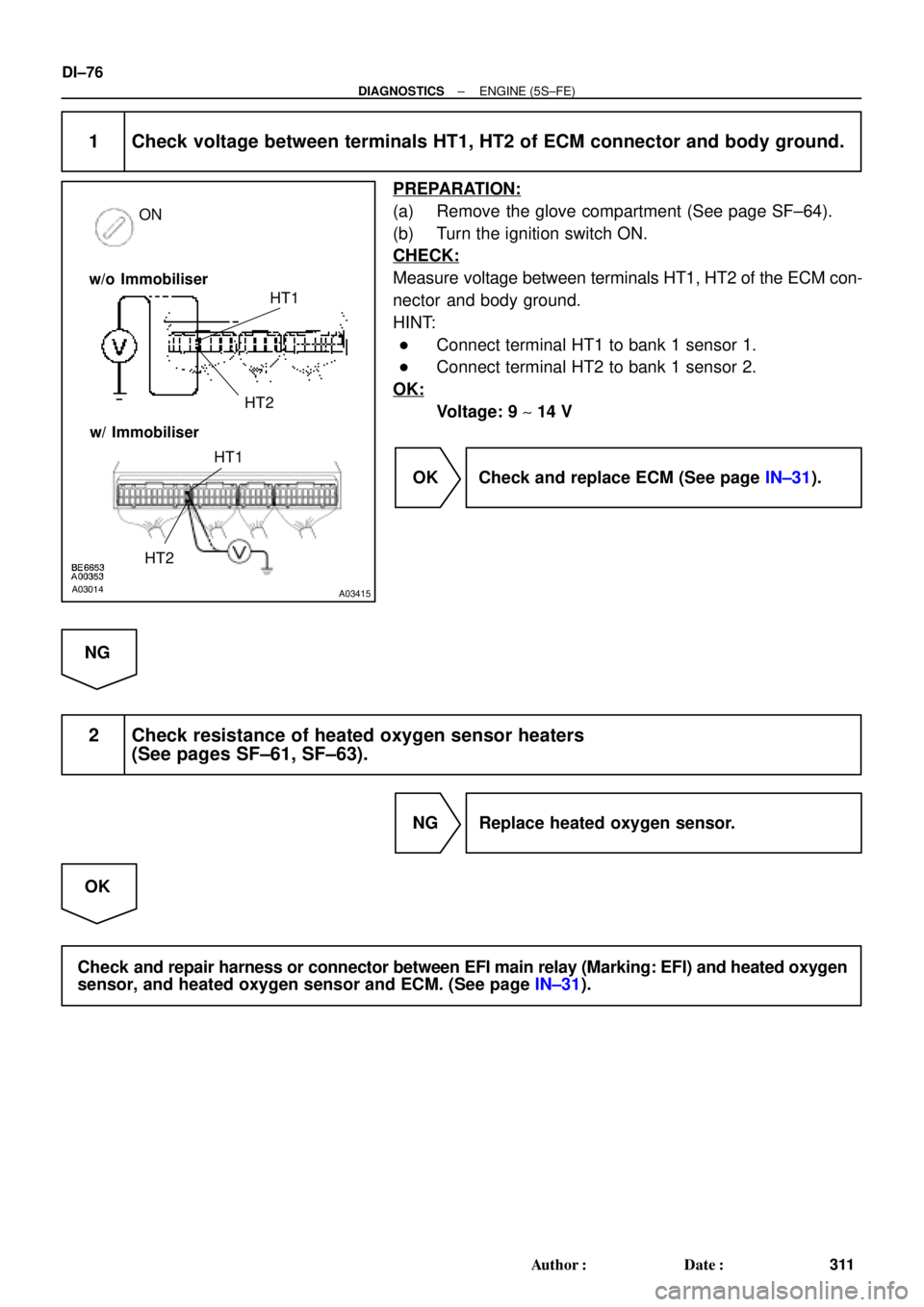
1 Check voltage between terminals HT1, HT2 of ECM connector and body ground.
PREPARATION:
(a) Remove the glove compartment (See page SF±64).
(b) Turn the ignition switch ON.
CHECK:
Measure voltage between terminals HT1, HT2 of the ECM con-
nector and body ground.
HINT:
�Connect terminal HT1 to bank 1 sensor 1.
�Connect terminal HT2 to bank 1 sensor 2.
OK:
Voltage: 9 ~ 14 V
OK Check and replace ECM (See page IN±31).
NG
2 Check resistance of heated oxygen sensor heaters
(See pages SF±61, SF±63).
NG Replace heated oxygen sensor.
OK
Check and repair harness or connector between EFI main relay (Marking: EFI) and heated oxygen
sensor, and heated oxygen sensor and ECM. (See page IN±31).