Page 3696 of 4770

V07268
VIBRATION METHOD: When vibration seems to be the major cause.
CONNECTORS
WIRE HARNESS
PARTS AND SENSOR1
Slightly shake the connector vertically and horizontally.
Slightly shake the wire harness vertically and horizontally.
The connector joint, fulcrum of the vibration, and body
through portion are the major areas to be checked thorough-
ly.
Apply slight vibration with a finger to the part of the sensor
considered to be the problem cause and check that the mal-
function occurs.Shake Slightly
Swing Slightly
Vibrate Slightly
HINT:
Applying strong vibration to relays may result in open relays.
± INTRODUCTIONHOW TO TROUBLESHOOT ECU CONTROLLED
SYSTEMSIN±25
25 Author�: Date�:
3. SYMPTOM SIMULATION
The most difficult case in troubleshooting is when there are no problem symptoms occurring. In such cases,
a thorough customer problem analysis must be carried out, then simulate the same or similar conditions and
environment in which the problem occurred in the customer's vehicle. No matter how much experience a
technician has, or how skilled he may be, if he proceeds to troubleshoot without confirming the problem
symptoms he will tend to overlook something important in the repair operation and make a wrong guess
somewhere, which will only lead to a standstill. For example, for a problem which only occurs when the en-
gine is cold, or for a problem which occurs due to vibration caused by the road during driving, etc., the prob-
lem can never be determined so long as the symptoms are confirmed with the engine hot condition or the
vehicle at a standstill. Since vibration, heat or water penetration (moisture) is likely cause for problem which
is difficult to reproduce, the symptom simulation tests introduced here are effective measures in that the ex-
ternal causes are applied to the vehicle in a stopped condition.
Important Points in the Symptom Simulation Test:
In the symptom simulation test, the problem symptoms should of course be confirmed, but the problem area
or parts must also be found out. To do this, narrow down the possible problem circuits according to the symp-
toms before starting this test and connect a tester beforehand. After that, carry out the symptom simulation
test, judging whether the circuit being tested is defective or normal and also confirming the problem symp-
toms at the same time. Refer to the problem symptoms table for each system to narrow down the possible
causes of the symptom.
Page 3699 of 4770

IN±28± INTRODUCTIONHOW TO TROUBLESHOOT ECU CONTROLLED
SYSTEMS
28 Author�: Date�:
5. PROBLEM SYMPTOMS TABLE
The suspected circuits or parts for each problem symptom are shown in the table below. Use this table to
troubleshoot the problem when a ºNormalº code is displayed in the diagnostic trouble code check but the
problem is still occurring. Numbers in the table indicate the inspection order in which the circuits or parts
should be checked.
HINT:
When the problem is not detected by the diagnostic system even though the problem symptom is present,
it is considered that the problem is occurring outside the detection range of the diagnostic system, or that
the problem is occurring in a system other than the diagnostic system.
Symptom
Suspect AreaSee page
Engine does not crank (Does not start)
No initial combustion (Does not start)
No complete combustion (Does not start)1. Starter and starter relay
1. ECM power source circuit
2. Fuel pump control circuit
3. Engine control module (ECM)
1. Starter signal circuit
2. Fuel pump control circuit1. Fuel pump control circuitDI±147
DI±151
IN±29
PROBLEM SYMPTOMS TABLE
1. Compression
2. Fuel pump control circuit 1. A/C signal circuit
2. Fuel pump control circuit 1. A/C signal circuit (Compressor circuit)
2. ECM power source circuit 1. Starter signal circuit
2. Fuel pump control circuit1. Starter signal circuit
2. Fuel pump control circuit
3. Compression
idling) High engine idle speed (Poor idling) Hot engine Cold engine (Difficult to start)Engine cranks normally (Difficult to start)
AC±88 DI±144
DI±151
EM±3 DI±151
� Problem Symptom� Page
Indicates the page where the flow chart for each circuit
is located.
� Circuit Inspection, Inspection Order
Indicates the circuit which needs to be checked for each problem
symptom. Check in the order indicated by the numbers.
� Circuit or Part Name
Indicates the circuit or part which needs to be checked.
ST±2
ST±17
DI±144
DI±151
DI±144
DI±151
Page 3710 of 4770

± INTRODUCTIONTERMS
IN±39
39 Author�: Date�:
OHVOverhead Valve
OPTOption
O/SOversize
P & BVProportioning And Bypass Valve
PCSPower Control System
PCVPositive Crankcase Ventilation
PKBParking Brake
PPSProgressive Power Steering
PSPower Steering
PTOPower Take±Off
R & PRack And Pinion
R/BRelay Block
RBSRecirculating Ball Type Steering
R/FReinforcement
RFSRigid Front Suspension
RRSRigid Rear Suspension
RHRight±Hand
RHDRight±Hand Drive
RLYRelay
ROMRead Only Memory
RrRear
RRRear±Engine Rear±Wheel Drive
RWDRear±Wheel Drive
SDNSedan
SENSensor
SICSStarting Injection Control System
SOCState Of Charge
SOHCSingle Overhead Camshaft
SPECSpecification
SPISingle Point Injection
SRSSupplemental Restraint System
SSMSpecial Service Materials
SSTSpecial Service Tools
STDStandard
STJCold±Start Fuel Injection
SWSwitch
SYSSystem
T/ATransaxle
TACHTachometer
TBIThrottle Body Electronic Fuel Injection
TCTurbocharger
TCCSTOYOTA Computer±Controlled System
TCVTiming Control Valve
TDCTop Dead Center
TEMP.Temperature
TEMSTOYOTA Electronic Modulated Suspension
Page 3713 of 4770

IACIdle Air ControlIdle Speed Control (ISC)
IATIntake Air TemperatureIntake or Inlet Air Temperature")
IN±42
± INTRODUCTIONTERMS
42 Author�: Date�:
HO2SHeated Oxygen SensorHeated Oxygen Sensor (HO2S)
IACIdle Air ControlIdle Speed Control (ISC)
IATIntake Air TemperatureIntake or Inlet Air Temperature
ICMIgnition Control Module±
IFIIndirect Fuel InjectionIndirect Injection (IDL)
IFSInertia Fuel±Shutoff±
ISCIdle Speed Control±
KSKnock SensorKnock Sensor
MAFMass Air FlowAir Flow Meter
MAPManifold Absolute PressureManifold Pressure
Intake Vacuum
MCMixture Control
Electric Bleed Air Control Valve (EBCV)
Mixture Control Valve (MCV)
Electric Air Control Valve (EACV)
MDPManifold Differential Pressure±
MFIMultiport Fuel InjectionElectronic Fuel Injection (EFI)
MILMalfunction Indicator LampCheck Engine Lamp
MSTManifold Surface Temperature±
MVZManifold Vacuum Zone±
NVRAMNon±Volatile Random Access Memory±
O2SOxygen SensorOxygen Sensor, O2 Sensor (O2S)
OBDOn±Board DiagnosticOn±Board Diagnostic System (OBD)
OCOxidation Catalytic ConverterOxidation Catalyst Convert (OC), CCo
OPOpen LoopOpen Loop
PAIRPulsed Secondary Air InjectionAir Suction (AS)
PCMPowertrain Control Module±
PNPPark/Neutral Position±
PROMProgrammable Read Only Memory±
PSPPower Steering Pressure±
PTOXPeriodic Trap OxidizerDiesel Particulate Filter (DPF)
Diesel Particulate Trap (DPT)
RAMRandom Access MemoryRandom Access Memory (RAM)
RMRelay Module±
ROMRead Only MemoryRead Only Memory (ROM)
RPMEngine SpeedEngine Speed
SCSuperchargerSupercharger
SCBSupercharger BypassE±ABV
SFISequential Multiport Fuel InjectionElectronic Fuel Injection (EFI), Sequential Injection
SPLSmoke Puff Limiter±
SRIService Reminder Indicator±
SRTSystem Readiness Test±
STScan Tool±
TBThrottle BodyThrottle Body
TBIThrottle Body Fuel InjectionSingle Point Injection
Central Fuel Injection (Ci)
TCTurbochargerTurbocharger
TCCTorque Converter ClutchTorque Converter
Page 3954 of 4770
PP0L0±01
± PREPARATIONBODY ELECTRICAL
PP±103
155 Author�: Date�:
EQUIPMENT
Voltmeter
Ammeter
Ohmmeter
Test lead
SyphonBrake fluid level warning switch
Bulb (3.4 W)Fuel sender gauge, Seat belt warning relay
Bulb (21 W)Turn signal flasher relay
Dry cell batteryFuel sender gauge
Torque wrench
Masking tapeRear window defogger wire
Tin foilRear window defogger wire
Page 4040 of 4770
FUEL PUMP
1439 Author�: Date�:
FUEL PUMP
ON±VEHICLE INSPECTION
1. CHECK FUEL PUMP OPERATION
(a) Connect a TOYOTA hand±held tester")
S05331
SF0D7±03
S05327
Fuel Inlet Hose
S05522
SF±6
± SFI (5S±FE)FUEL PUMP
1439 Author�: Date�:
FUEL PUMP
ON±VEHICLE INSPECTION
1. CHECK FUEL PUMP OPERATION
(a) Connect a TOYOTA hand±held tester to the DLC3.
(b) Turn the ignition switch ON and push the TOYOTA hand±
held tester main switch ON.
NOTICE:
Do not start the engine.
(c) Select the ACTIVE TEST mode on the TOYOTA hand±
held tester.
(d) Please refer to the TOYOTA hand±held tester operator's
manual for further details.
(e) If you have no TOYOTA hand±held tester, connect the
positive (+) and negative (±) leads from the battery to the
fuel pump connector. (See step 7)
(f) Check that there is pressure in the fuel inlet hose from the
fuel filter.
HINT:
If there is fuel pressure, you will hear the sound of fuel flowing.
If there is no pressure, check the fusible link, fuses, EFI main
relay, fuel pump, ECM and wiring connections.
(g) Turn the ignition switch OFF.
(h) Disconnect the TOYOTA hand±held tester from the
DLC3.
2. CHECK FUEL PRESSURE
(a) Check the battery positive voltage is above 12 V.
(b) Disconnect the negative (±) terminal cable from the bat-
tery.
(c) Remove the union bolt and 2 gaskets, and disconnect the
fuel inlet hose from the fuel filter outlet.
CAUTION:
�Put a shop towel under the fuel filter.
�Slowly loosen the union bolt.
Page 4074 of 4770
S05392
EFI Main
Relay
SF0DX±03
S04970
Continuity
No ContinuityOhmmeter
2
35 Ohmmeter
1
S04969ContinuityOhmmeter 2
35 1
Battery SF±40
± SFI (5S±FE)EFI MAIN RELAY
1473 Author�: Date�:
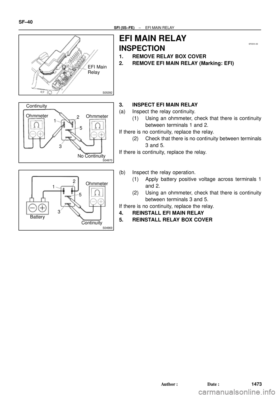
EFI MAIN RELAY
INSPECTION
1. REMOVE RELAY BOX COVER
2. REMOVE EFI MAIN RELAY (Marking: EFI)
3. INSPECT EFI MAIN RELAY
(a) Inspect the relay continuity.
(1) Using an ohmmeter, check that there is continuity
between terminals 1 and 2.
If there is no continuity, replace the relay.
(2) Check that there is no continuity between terminals
3 and 5.
If there is continuity, replace the relay.
(b) Inspect the relay operation.
(1) Apply battery positive voltage across terminals 1
and 2.
(2) Using an ohmmeter, check that there is continuity
between terminals 3 and 5.
If there is no continuity, replace the relay.
4. REINSTALL EFI MAIN RELAY
5. REINSTALL RELAY BOX COVER
Page 4075 of 4770
S05389
Circuit Opening
RelaySF0DY±03
S04970
Continuity
Ohmmeter
1
35 2Ohmmeter
No Continuity
S04969ContinuityOhmmeter
1
35 2
Battery
± SFI (5S±FE)CIRCUIT OPENING RELAY
SF±41
1474 Author�: Date�:
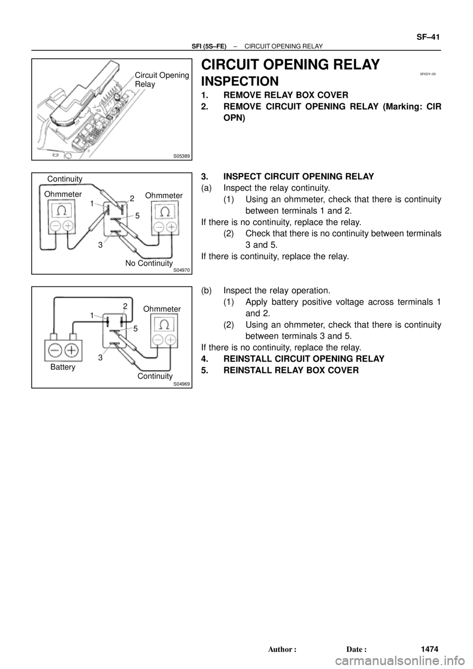
CIRCUIT OPENING RELAY
INSPECTION
1. REMOVE RELAY BOX COVER
2. REMOVE CIRCUIT OPENING RELAY (Marking: CIR
OPN)
3. INSPECT CIRCUIT OPENING RELAY
(a) Inspect the relay continuity.
(1) Using an ohmmeter, check that there is continuity
between terminals 1 and 2.
If there is no continuity, replace the relay.
(2) Check that there is no continuity between terminals
3 and 5.
If there is continuity, replace the relay.
(b) Inspect the relay operation.
(1) Apply battery positive voltage across terminals 1
and 2.
(2) Using an ohmmeter, check that there is continuity
between terminals 3 and 5.
If there is no continuity, replace the relay.
4. REINSTALL CIRCUIT OPENING RELAY
5. REINSTALL RELAY BOX COVER