Page 1513 of 4770

L PART NUMBER OF CONNECTORS
Code Part Name Part NumberCodePart Name Part Number
Note : Not all of the above part numbers of the connector are established for the supply. In case of ordering
a connector or terminal with wire, please confirm in advance if there is supply for it using ªParts Catalog
Newsº (published by Parts Engineering Administration Dept.).
J15Junction Connector90980±10803
J16Junction Connector90980±11661J17Junction Connector90980±11661
J18Junction Connector90980±11542J19Junction Connector90980±11542
J20Junction Connector90980±11539
J21Junction Connector90980±11542
J22Junction Connector90980±11539J23Junction Connector90980±11539
J24Junction Connector
J25Junction Connector90980±11529
J26Junction Connector
J27Junction Connector90980±11661J28Junction Connector90980±11661
J29Junction Connector90980±11502
J30Junction Connector90980±11661J31Junction Connector90980±11661
J32Junction Connector90980±10803
J33Junction Connector
J34Junction Connector90980±11661J35Junction Connector90980±11661
J36Junction Connector
J37Junction Connector90980±11542
J38Junction Connector90980±10803J39Junction Connector90980±10803
J40Junction Connector90980±10976
K 1Knock Sensor 190980±11166K 2Knock Sensor 290980±11166
K 3Key Interlock Solenoid90980±10825
L 1License Plate Light LH90980±11148L 2License Plate Light RH90980±11148
L 3Light Failure Sensor90980±10803
L 4Luggage Compartment Key Unlock SW90980±11212
L 5Luggage Compartment Light90980±11148
L 6Luggage Compartment Light SW90980±11097
M 1Manifold Absolute Pressure Sensor90980±10845
M 2Mass Air Flow Meter90980±11317
M 3Moon Roof Control SW and Relay90980±10799
M 4Moon Roof Motor and Limit SW90980±11011
N 1Noise Filter (Ignition)90980±10843
N 2Noise Filter (Rear Window Defogger)90980±11259
O 1Oil Pressure SW90980±11363
O 2O/D Main SW and A/T Shift Lever
Illumination90980±10795
P 1Park/Neutral Position SW,A/T Indicator Light
SW and Back±Up Light SW90980±11332
P 2Power Steering Oil Pressure SW90980±11428
P 3Parking Brake SW90980±10871
P 4Power Outlet90980±10760
P 5Personal Light90980±10825
P 6Power Window Control SW Front RH90980±10789
P 7Power Window Control SW Rear LH90980±10631P 8Power Window Control SW Rear RH90980±10631
P 9Power Window Master SW and Door Lock
Control SW LH90980±10807
P10Power Window Motor Front LH
P11Power Window Motor Front RH90980±10860P12Power Window Motor Rear LH90980±10860
P13Power Window Motor Rear RH
P14Power Seat Control SW (Driver's Seat)
P15Power Seat Control SW
(Front Passenger's Seat)90980±10803
P16Power Seat Motor
(Driver's Seat Rear Vertical Control)
P17Power Seat Motor
(Driver's Seat Reclining Control)90980±10825
P18Power Seat Motor
(Driver's Seat Slide Control)
P19Power Seat Motors (Driver's Seat)90980±11001
P20Power Seat Motor (Front Passenger's Seat
Rear Vertical Control)
P21Power Seat Motor (Front Passenger's Seat
Reclining Control)90980±10825
P22Power Seat Motor (Front Passenger's Seat
Slide Control)
P23Power Seat Motors
(Front Passenger's Seat)90980±11001
P24Pretensioner LH90980±11862P25Pretensioner RH90980±11862
R 1Radiator Fan Motor90980±10928
R 2Radio and Player90980±10996
R 3Radio and Player90980±10997
R 4Radio and Player90980±11264
R 5Rear Window Defogger SW90980±11280
R 6Remote Control Mirror SW90980±11450
R 7Rheostat90980±10908
R 8Rear Combination Light LH90980±10795
R 9Rear Combination Light LH90980±11001
R10Rear Combination Light RH90980±10795
R11Rear Combination Light RH90980±11001
Page 1515 of 4770
AC2CK±01
± AIR CONDITIONINGAIR CONDITIONING CONTROL ASSEMBLY (Manual
A/C)AC±93
2581 Author�: Date�:
2001 CAMRY (RM819U)
AIR CONDITIONING CONTROL ASSEMBLY (Manual A/C)
ON±VEHICLE INSPECTION
INSPECT HEATER CONTROL DIALS OPERATION
Turn the control lever and dials left and right then check that click sound can be heard and recoil is felt.
If click sound can not be heard or recoil is felt, adjust the control cable or check control cable and heater
control assembly.
Page 1523 of 4770

AC2810
AC0LG±02
AC2811
N11084
Wrong Okey
HI LO HILO
± AIR CONDITIONINGAIR CONDITIONING SYSTEM
AC±1
2483 Author�: Date�:
AIR CONDITIONING SYSTEM
PRECAUTION
1. DO NOT HANDLE REFRIGERANT IN AN ENCLOSED
AREA OR WEAR EYE PROTECTION
2. ALWAYS WEAR EYE PROTECTION
3. BE CAREFUL NOT TO GET LIQUID REFRIGERANT IN
YOUR EYES OR ON YOUR SKIN
If liquid refrigerant gets in your eyes or on your skin.
(a) Wash the area with lots of cool water.
CAUTION:
Do not rub your eyes or skin.
(b) Apply clean petroleum jelly to the skin.
(c) Go immediately to a physician or hospital for professional
treatment.
4. NEVER HEAT CONTAINER OR EXPOSE IT TO NAKED
FLAME
5. BE CAREFUL NOT TO DROP CONTAINER AND NOT
TO APPLY PHYSICAL SHOCKS TO IT
6. DO NOT OPERATE COMPRESSOR WITHOUT
ENOUGH REFRIGERANT IN REFRIGERATION SYS-
TEM
If there is not enough refrigerant in the refrigerant system oil lu-
brication will be insufficient and compressor burnout may occur,
so that care to avoid this, necessary care should be taken.
7. DO NOT OPEN PRESSURE MANIFOLD VALVE WHILE
COMPRESSOR IS OPERATE
If the high pressure valve is opened, refrigerant flows in the re-
verse direction and could cause the charging cylinder to rup-
ture, so open and close the only low pressure valve.
8. BE CAREFUL NOT TO OVERCHARGE SYSTEM WITH
REFRIGERANT
If refrigerant is overcharged, it causes problems such as insuffi-
cient cooling, poor fuel economy, engine overheating etc.
Page 1529 of 4770

I01390
Condition: Insufficient cooling
I01392
Condition: Insufficient cooling
NOTE : These gauge indica-
tions are shown when the
refrigeration system has
been opened and the refrig-
erant charged without vacu-
um purging.
± AIR CONDITIONINGAIR CONDITIONING SYSTEM
AC±7
2489 Author�: Date�:
(6) Refrigerant overcharged or insufficient cooling of
condenser
Symptom seen in
refrigeration systemProbable causeDiagnosisRemedy
� Pressure too high on both low
and high pressure sides
� No air bubbles seen through the
sight glass even when the engine
rpm is lowered� Unable to develop sufficient per-
formance due to excessive refrig-
eration system
� Insufficient cooling of condenser� Excessive refrigerant in
cycle " refrigerant over charged
� Condenser cooling " condenser
fins clogged of condenser fan
faulty
(1) Clean condenser
(2) Check condenser fan motor
operation
(3) If (1) and (2) are in normal
state, check amount of refrigerant
Charge proper amount of refriger-
ant
(7) Air present in refrigeration system
Symptom seen in
refrigeration systemProbable causeDiagnosisRemedy
� Pressure too high on both low
and high pressure sides
� The low pressure piping hot to
touch
� Bubbles seen in sight glass
Air entered in refrigeration system
� Air present in refrigeration sys-
tem
� Insufficient vacuum purging
(1) Check compressor oil to see if
it is dirty or insufficient
(2) Evacuate air and charge new
refrigerant
Page 1550 of 4770

I03838
SST
I03839
PushSST
Pull
SST
Release
Lever
I06919
Disconnect the tube
using hand
Screw
Driver
Tube
I06878
Correct Wrong
Gap
N20281
AC±28
± AIR CONDITIONINGAIR CONDITIONING UNIT
2510 Author�: Date�:
(1) Inert SST to piping clamp.
HINT:
Confirm the direction of the piping clamp claw and SST using
the illustration showing on the caution label.
(2) Push down SST and release the clamp lock.
NOTICE:
Be careful not to deform the tubes, when pushing SST.
(3) Pull SST slightly and push the release lever, then re-
move the piping clamp with SST.
(4) Remove the piping clamp from SST.
(b) Disconnect the both tubes.
NOTICE:
�Do not use tools like screwdriver to remove the tube.
�Cap the open fittings immediately to keep moisture or
dirt out of the system.
HINT:
At the time of installation, please refer to the following item.
�Lubricate 4 new O±rings with compressor oil and install
the tubes.
�After connection, check the fitting for claw of the piping
clamp.
7. REMOVE A/C UNIT
(a) Disconnect the connector.
(b) Slide the floor carpet backward.
(c) Remove the rear heater duct.
(d) Remove the 2 nuts and A/C unit.
Page 1553 of 4770
 Install the p")
AC0LX±02
N21046
N21045
Packing Paper
N21044
± AIR CONDITIONINGAIR CONDITIONING UNIT
AC±31
2513 Author�: Date�:
REASSEMBLY
1. INSTALL THERMISTOR TO EVAPORATOR
2. INSTALL EVAPORATOR
(a) Install the plate to the evaporator.
(b) Install the evaporator on the insulator.
(c) Connect the heater case with the 13 screws.
NOTICE:
The packing for water seal should be replaced, with a new
one when the A/C unit is reassembled.
(d) Install the 2 new packings.
(e) Install the grommet to evaporator.
HINT:
If evaporator is replaced, add compressor oil to the compressor.
Add 40 ± 50 cc (1.4 ± 1.7 fl.oz.)
Compressor oil: ND ± OIL 8 or equivalent
3. INSTALL EXPANSION VALVE
(a) Lubricate 2 new O±rings with compressor oil and install
the tubes.
(b) Install the liquid tube and suction tube on the expansion
valve.
(c) Using a knife, cut off packing paper of packing while peel
off the paper, as shown in the illustration.
HINT:
Leave the packing paper untaped on the tube side so that the
installation bolt hole for remains visible.
(d) Apply new packing.
NOTICE:
Do not overtape the packing beyond the expansion valve
edge.
Page 1554 of 4770
N20283
N20245
Pin
Pin AC±32
± AIR CONDITIONINGAIR CONDITIONING UNIT
2514 Author�: Date�:
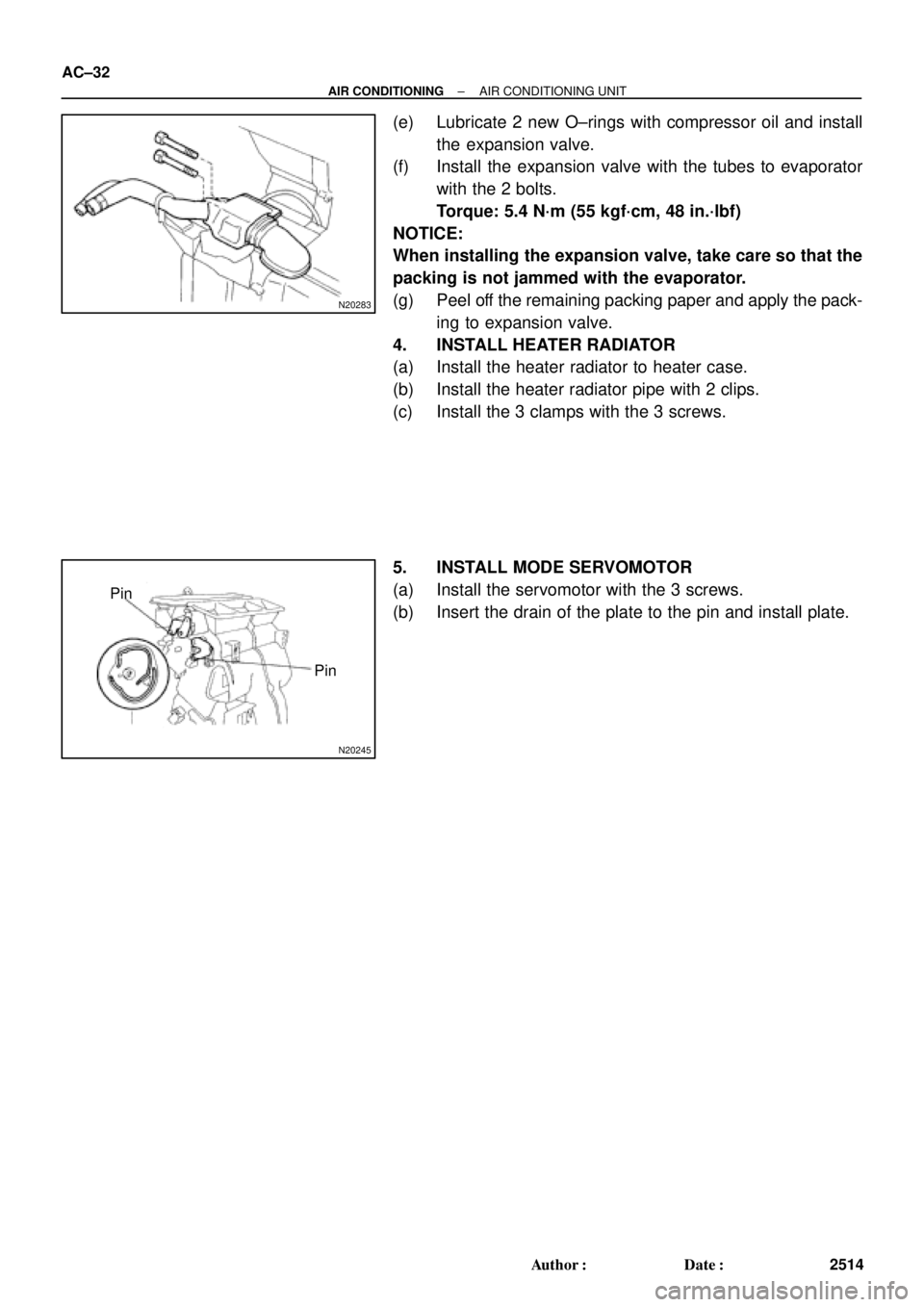
(e) Lubricate 2 new O±rings with compressor oil and install
the expansion valve.
(f) Install the expansion valve with the tubes to evaporator
with the 2 bolts.
Torque: 5.4 N´m (55 kgf´cm, 48 in.´lbf)
NOTICE:
When installing the expansion valve, take care so that the
packing is not jammed with the evaporator.
(g) Peel off the remaining packing paper and apply the pack-
ing to expansion valve.
4. INSTALL HEATER RADIATOR
(a) Install the heater radiator to heater case.
(b) Install the heater radiator pipe with 2 clips.
(c) Install the 3 clamps with the 3 screws.
5. INSTALL MODE SERVOMOTOR
(a) Install the servomotor with the 3 screws.
(b) Insert the drain of the plate to the pin and install plate.
Page 1561 of 4770

AC0M4±02
N01143
W
N01150
± AIR CONDITIONINGCOMPRESSOR AND MAGNETIC CLUTCH
AC±39
2521 Author�: Date�:
COMPRESSOR AND MAGNETIC
CLUTCH
ON±VEHICLE INSPECTION
1. INSPECT COMPRESSOR FOR METALLIC SOUND
(a) Start engine.
(b) Check if there is a metallic sound from the compressor
when the A/C switch is on.
If metallic sound is heard, replace the compressor assembly.
2. INSPECT REFRIGERANT PRESSURE
See ºON±VEHICLE INSPECTIONº of AIR CONDITIONING
SYSTEM on page AC±3.
3. INSPECT COMPRESSOR LOCK SENSOR RESIS-
TANCE
(a) Disconnect the connector.
(b) Measure resistance between terminals 1 and 2.
Standard resistance: 65 ± 125 W at 20 °C (68 °F)
If resistance is not as specified, replace the compressor assem-
bly.
4. INSPECT VISUALLY FOR LEAKAGE OF REFRIGER-
ANT FROM SAFETY SEAL
Using a gas leak detector, check for leakage of refrigerant.
If there is any leakage, replace the compressor assembly.
5. CHECK FOR LEAKAGE OF GREASE FROM CLUTCH
BEARING
6. CHECK FOR SIGNS OF OIL ON PRESSURE PLATE OR
ROTOR
7. INSPECT MAGNETIC CLUTCH BEARING FOR NOISE
(a) Start engine.
(b) Check for abnormal noise from near the compressor
when the A/C switch is OFF.
If abnormal noise is being emitted, replace the magnetic clutch.
8. INSPECT MAGNETIC CLUTCH OPERATION
(a) Disconnect the connector.
(b) Connect the positive (+) lead from the battery to terminal
4 and the negative (±) lead to the body ground.
(c) Check that the magnetic clutch is energized.
If operation is not as specified, replace the magnetic clutch.