2000 TOYOTA CAMRY oil
[x] Cancel search: oilPage 1241 of 4770
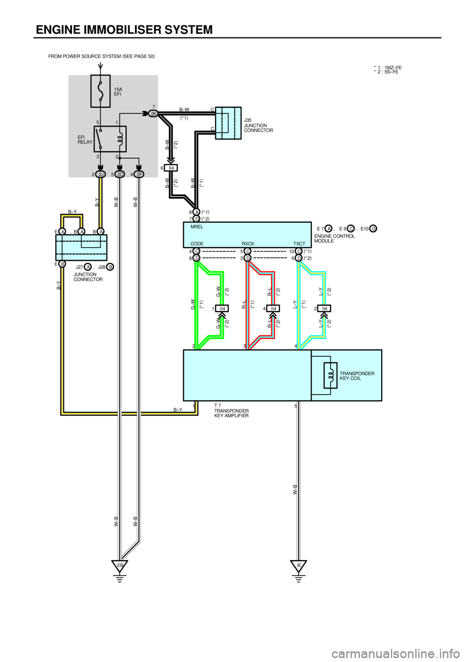
ENGINE IMMOBILISER SYSTEM
15A
EFI
32 51
2J 22C52F42K7
II4 6
D 7(
*2) A 8(
*1)
D 8C 4
D 3C 5
D 9(
*2) C 10(
*1)
II4 1 II44II42 B EA EAB A B
EBIE B±W
(
*1)
B±W
(
*2) B±W
(
*2)
B±W
(
*1) W±B
W±BB±Y
G± W
(
*2)
R±L
(
*2)
L±Y
(
*2) L±Y
(
*2) R±L
(
*2) G± W
(
*2)G±W
(
*1)
W±B
CODE RXCK TXCTMREL FROM POWER SOURCE SY STEM (
SEE PAGE 50)
EFI
RELAY
B±Y
L±Y
(
*1) R±L
(
*1)
E 7
ENGINE CONTROL
MODULEC A, E 9 D, E10
B±Y
J27
JUNCTION
CONNECTORB A, J28
5 1 234
B±YTRANSPONDER
KEY COIL
TRANS PONDER
KEY AMPLIFIER T 7
W± B W± B
* 1 : 1MZ± FE
* 2 : 5S±FE
JUNCTION
CONNECTOR J35 C
C
Page 1251 of 4770

HEADLIGHT (w/ DAYTIME RUNNING LIGHT)
The current from the FL MAIN is always flowing from the MAIN fuse to HEAD relay (Coil side) to TERMINAL H±LP of the
daytime running light relay (Main), from DOME fuse to TERMINAL +B of the daytime running light relay (Main) and from the
ALT fuse to Taillight relay (Coil side) to TERMINAL TAIL (TMMK Made) of the daytime running light relay (Main).
When the ignition SW is turned on, the current flowing through the GAUGE fuse flows to TERMINAL IG of the daytime
running light relay (Main).
1. DAYTIME RUNNING LIGHT OPERATION
When the engine is started, voltage generated at TERMINAL L of the generator is applied to TERMINAL CHG± of the
daytime running light relay (Main). If the parking brake lever is pulled up (Parking brake SW on) at this time, the relay is not
activated so the daytime running light system does not operate. If the parking brake lever is then released (Parking brake
SW off), a signal is input to TERMINAL PKB of the relay.
This activates the daytime running light relay (Main) and the HEAD relay is turned to on, so the current flows from the MAIN
fuse to the HEAD relay (Point side) to TERMINAL 1 of the DIM relay to TERMINAL 4 to H±LP LH (LWR), H±LP RH (LWR)
fuses to TERMINAL 1 of the headlights to TERMINAL 3 to TERMINAL 1 of the daytime running light resistor to TERMINAL 2
to GROUND, causing the headlights to light up (Headlights light up dimmer than normal brightness.). Once the daytime
running light system operates and the headlights light up, the headlights remain on even if the parking brake lever is pulled
up (Parking brake SW on).
If the engine stalls and the ignition SW remains on, the headlights remain light up even through current is no longer output
from TERMINAL L of the generator. If the ignition SW is then turned off, the headlights go off.
If the engine is started with the parking brake lever released (Parking brake SW off), the daytime running light system
operates and headlights light up when the engine starts.
2. HEADLIGHT OPERATION
When the light control SW is switched to HEAD position and the dimmer SW is set to LOW position, causing the daytime
running light relay (Main) and the HEAD relay to turn on, so the current flows from the MAIN fuse to HEAD relay (Point side)
to DRL NO.2 fuse to TERMINAL 3 of the DRL NO.4 relay to TERMINAL 4 to TERMINAL H±ON of the daytime running light
relay (Main) to TERMINAL H to TERMINAL 3 of the integration relay to TERMINAL 4 to TERMINAL 13 of the light control
SW to TERMINAL 16 to GROUND, activating the DRL. NO.4 relay. The current to HEAD relay (Point side) then flows to
TERMINAL 1 of the DIM relay to TERMINAL 4 to H±LP LH (LWR), H±LP RH (LWR) fuses to TERMINAL 1 of the headlights
to TERMINAL 3 to TERMINAL 1 of the DRL NO.4 relay to TERMINAL 2 to GROUND, causing the headlights to light up at
normal intensity.
When the light control SW is switched to HEAD position and the dimmer SW is set to HIGH position, the signal from the
dimmer SW is input to the daytime running light relay (Main). This activates the daytime running light relay (Main) and the
HEAD relay is turned on, so the current flows from the MAIN fuse to HEAD relay (Point side) to TERMINAL 1 of the DIM
relay to TERMINAL 3 to TERMINAL DIM of the daytime running light relay (Main), activating the DIM relay. This causes
current to flow from TERMINAL 1 of the DIM relay to TERMINAL 2 to HEAD LH (UPR), HEAD RH (UPR) fuses to TERMINAL
2 of the headlights to TERMINAL 3 to TERMINAL 1 of the DRL NO.4 relay to TERMINAL 2 to GROUND, causing the
headlights to light up at high beam and the high beam indicator light to light up.
When the dimmer SW is switched to FLASH position, the signal from the dimmer SW is input to the daytime running light
relay (Main). This activates the daytime running light relay (Main) and the HEAD relay is turned on, so the current flows from
the MAIN fuse to HEAD relay (Point side) to DRL NO.2 fuse to TERMINAL 3 of the DRL NO.4 relay to TERMINAL 4 to
TERMINAL H±ON of the daytime running light relay (Main) to TERMINAL H to TERMINAL 8 of the dimmer SW to
TERMINAL 16 to GROUND, activating the DRL NO.4 relay. At the same time, the current flows from the TERMINAL 1 of the
DIM relay to TERMINAL 3 to TERMINAL DIM of the daytime running light relay (Main), activating the DIM relay, and also
flows from the HEAD LH (UPR), HEAD RH (UPR) fuses to TERMINAL 2 of the headlights to TERMINAL 3 to TERMINAL 1 of
the DRL NO.4 relay to TERMINAL 2 to GROUND, causing the headlights to light up at high beam and the high beam
indicator light to light up.
SYSTEM OUTLINE
Page 1252 of 4770
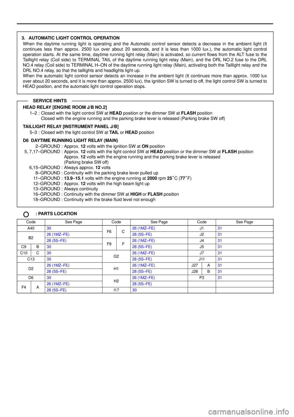
3. AUTOMATIC LIGHT CONTROL OPERATION
When the daytime running light is operating and the Automatic control sensor detects a decrease in the ambient light (It
continues less than approx. 2500 lux over about 20 seconds, and it is less than 1000 lux.), the automatic light control
operation starts. At the same time, daytime running light relay (Main) is activated, so current flows from the ALT fuse to the
Taillight relay (Coil side) to TERMINAL TAIL of the daytime running light relay (Main), and the DRL NO.2 fuse to the DRL
NO.4 relay (Coil side) to TERMINAL H±ON of the daytime running light relay (Main), activating both the Taillight relay and the
DRL NO.4 relay, so that the taillights and headlights light up.
When the automatic light control sensor detects an increase in the ambient light (It continues more than approx. 1000 lux
over about 20 seconds, and it is more than approx. 2500 lux), the ignition SW is turned to off, the light control SW is turned to
HEAD position, and the automatic light control operation stops.
HEAD RELAY [ENGINE ROOM J/B NO.2]
1±2 : Closed with the light control SW at HEAD position or the dimmer SW at FLASH position
Closed with the engine running and the parking brake lever is released (Parking brake SW off)
TAILLIGHT RELAY [INSTRUMENT PANEL J/B]
5±3 : Closed with the light control SW at TAIL or HEAD position
D6 DAYTIME RUNNING LIGHT RELAY (MAIN)
2±GROUND : Approx. 12 volts with the ignition SW at ON position
5, 7,17±GROUND : Approx. 12 volts with the light control SW at HEAD position or the dimmer SW at FLASH position
Approx. 12 volts with the engine running and the parking brake lever is released
(Parking brake SW off)
6,15±GROUND : Always approx. 12 volts
8±GROUND : Continuity with the parking brake lever pulled up
11±GROUND :13.9±15.1 volts with the engine running at 2000 rpm 25°C (77°F)
12±GROUND : Approx. 12 volts with the high beam light up
13±GROUND : Always continuity
16±GROUND : Continuity with the dimmer SW at HIGH or FLASH position
18±GROUND : Continuity with the brake fluid level not enough
: PARTS LOCATION
CodeSee PageCodeSee PageCodeSee Page
A4030F6C26 (1MZ±FE)J131
B226 (1MZ±FE)F6C28 (5S±FE)J231B228 (5S±FE)F9F26 (1MZ±FE)J431
C9B30F9F28 (5S±FE)J531
C10C30G226 (1MZ±FE)J731
C1330G228 (5S±FE)J1131
D226 (1MZ±FE)H126 (1MZ±FE)J27A31D228 (5S±FE)H128 (5S±FE)J28B31
D630H226 (1MZ±FE)P331
F4A26 (1MZ±FE)H228 (5S±FE)F4A28 (5S±FE)I1730
SERVICE HINTS
Page 1258 of 4770
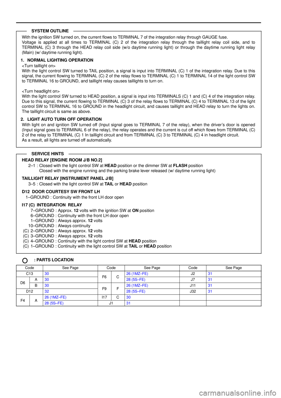
With the ignition SW turned on, the current flows to TERMINAL 7 of the integration relay through GAUGE fuse.
Voltage is applied at all times to TERMINAL (C) 2 of the integration relay through the taillight relay coil side, and to
TERMINAL (C) 3 through the HEAD relay coil side (w/o daytime running light) or through the daytime running light relay
(Main) (w/ daytime running light).
1. NORMAL LIGHTING OPERATION
With the light control SW turned to TAIL position, a signal is input into TERMINAL (C) 1 of the integration relay. Due to this
signal, the current flowing to TERMINAL (C) 2 of the relay flows to TERMINAL (C) 1 to TERMINAL 14 of the light control SW
to TERMINAL 16 to GROUND, and taillight relay causes taillights to turn on.
With the light control SW turned to HEAD position, a signal is input into TERMINALS (C) 1 and (C) 4 of the integration relay.
Due to this signal, the current flowing to TERMINAL (C) 3 of the relay flows to TERMINAL (C) 4 to TERMINAL 13 of the light
control SW to TERMINAL 16 to GROUND in the headlight circuit, and causes taillight and HEAD relay to turn the lights on.
The taillight circuit is same as above.
2. LIGHT AUTO TURN OFF OPERATION
With light on and ignition SW turned off (Input signal goes to TERMINAL 7 of the relay), when the driver's door is opened
(Input signal goes to TERMINAL 6 of the relay), the relay operates and the current is cut off which flows from TERMINAL (C)
2 of the relay to TERMINAL (C) 1 In taillight circuit and from TERMINAL (C) 3 to TERMINAL (C) 4 in headlight circuit.
As a result, all lights are turned off automatically.
HEAD RELAY [ENGINE ROOM J/B NO.2]
2±1 : Closed with the light control SW at HEAD position or the dimmer SW at FLASH position
Closed with the engine running and the parking brake lever released (w/ daytime running light)
TAILLIGHT RELAY [INSTRUMENT PANEL J/B]
3±5 : Closed with the light control SW at TAIL or HEAD position
D12 DOOR COURTESY SW FRONT LH
1±GROUND : Continuity with the front LH door open
I17 (C)
INTEGRATION RELAY
7±GROUND : Approx. 12 volts with the ignition SW at ON position
6±GROUND : Continuity with the front LH door open
1±GROUND : Always approx. 12 volts
10±GROUND : Always continuity
(C) 2±GROUND : Always approx. 12 volts
(C) 3±GROUND : Always approx. 12 volts
(C) 4±GROUND : Continuity with the light control SW at HEAD position
(C) 1±GROUND : Continuity with the light control SW at TAIL or HEAD position
: PARTS LOCATION
CodeSee PageCodeSee PageCodeSee Page
C1330F6C26 (1MZ±FE)J231
D6A30F6C28 (5S±FE)J731D6B30F9F26 (1MZ±FE)J1131
D1232F9F28 (5S±FE)J3231
F4A26 (1MZ±FE)I17C30F4A28 (5S±FE)J131
SYSTEM OUTLINE
SERVICE HINTS
Page 1299 of 4770

DOOR LOCK CONTROL (TMC MADE)
Current always flows to TERMINAL (A) 13 (w/o theft deterrent system), (B) 1 (w/ theft deterrent system) of the integration
relay through the DOOR fuse.
When the ignition SW is turned on, the current flowing through the GAUGE Fuse flows to TERMINAL 7 of the integration
relay to TERMINAL (A) 12 (w/o theft deterrent system), (B) 3 (w/ theft deterrent system) to the power relay (Coil side) to
GROUND.
1. MANUAL LOCK OPERATION
When the door lock control SW or door key lock and unlock SW are operated to LOCK position, a lock signal is input to
TERMINAL (A) 1 or (A) 3 (w/o theft deterrent system), (B) 16 or (B) 18 (w/ theft deterrent system) of the integration relay and
causes the relay to function. Current flows from TERMINAL (A) 13 (w/o theft deterrent system), (B) 1 (w/ theft deterrent
system) of the relay to (A) 6 (w/o theft deterrent system), (B) 12 (w/ theft deterrent system) to TERMINAL 2 of the door lock
motors to TERMINAL 3 to TERMINAL (A) 7 (w/o theft deterrent system), (B) 11 and (B) 25 (w/ theft deterrent system) of the
relay to TERMINAL 10 to GROUND and the door lock motor causes the door to lock.
2. MANUAL UNLOCK OPERATION
When the door lock control SW or door key lock and unlock SW are operated to UNLOCK position, an unlock signal is input
to TERMINAL (A) 2, (A) 4 or (A) 5 (w/o theft deterrent system), (B) 17, (B) 19 or (B) 20 (w/ theft deterrent system) of the
integration relay and causes the relay to function. Current flows from TERMINAL (A) 13 (w/o theft deterrent system), (B) 1 (w/
theft deterrent system) of the relay to TERMINAL (A) 7 (w/o theft deterrent system), (B) 11 and (B) 25 (w/ theft deterrent
system) to TERMINAL 3 of the door lock motors to TERMINAL 2 to TERMINAL (A) 6 (w/o theft Deterrent system), (B) 12 (w/
theft deterrent system) of the relay to TERMINAL 10 to GROUND and door lock motors causes door to unlock.
3. DOUBLE OPERATION UNLOCK OPERATION
When the door key lock and unlock SW front LH is turned to the unlock side, only the driver's door is mechanically unlocked.
Turning the door key lock and unlock SW front LH to the unlock side causes a signal to be input to TERMINAL (A) 4 (w/o
theft deterrent system), (B) 19 (w/ theft deterrent system) of the relay, and if the signal is input again within 3 seconds by
turning the SW to the unlock side again, current flows from TERMINAL (A) 7 (w/o theft deterrent system), (B) 11 and (B) 25
(w/ theft deterrent system) of the integration relay to TERMINAL 3 of the door lock motors to TERMINAL 2 of the door lock
motors to TERMINAL (A) 6 (w/o theft deterrent system), (B) 12 (w/ theft deterrent system) of the relay to TERMINAL 10 to
GROUND, causing the door lock motors to operate and unlock the doors.
4. IGNITION KEY REMINDER OPERATION
*Operating door lock knob (Operation of door lock motors)
With ignition key in cylinder (Unlock warning SW on), when the door is opened and locked using door lock knob (Door
lock motor), the door is locked once but each door is unlocked soon by the function of the relay. As a result, the current
flows from TERMINAL (A) 13 (w/o theft deterrent system), (B) 1 (w/ theft deterrent system) of the integration relay to
TERMINAL (A) 7 (w/o theft deterrent system),(B) 11 and (B) 25 (w/ theft deterrent system) to TERMINAL 3 of the door
lock motors to TERMINAL 2 of the door lock motors to TERMINAL (A) 6 (w/o theft deterrent system), (B) 12 (w/ theft
deterrent system) of the relay to TERMINAL 10 to GROUND and causes all the doors to unlock.
*Operating door lock control SW or door key lock and unlock SW
With ignition key in cylinder (Unlock warning SW on), when the door is opened and locked using door lock control SW or
key SW, the door is locked once but each door is unlock by the function of SW contained in motors, which the signal is
input to TERMINAL (A) 9 or (A) 10 (w/o theft deterrent system), (B) 5 or (B) 7 (w/ theft deterrent system) of the relay.
According to this input signal, the current in ECU flows from TERMINAL (A) 13 (w/o theft deterrent system), (B) 1 (w/
theft deterrent system) of the relay to TERMINAL (A) 7 (w/o theft deterrent system), (B) 11 and (B) 25 (w/ theft deterrent
system) to TERMINAL 3 of the door lock motors to TERMINAL 2 of the door lock motors to TERMINAL (A) 6 (w/o theft
deterrent system), (B) 12 (w/ theft deterrent system) of the relay to TERMINAL 10 to GROUND and causes all the doors
to unlock.
*In case of key less lock
With ignition key in cylinder (Unlock warning SW on), when the unlock function is disturbed more than 0.2 seconds, for
example pushing the door lock knob etc., the door holds on lock condition. Closing the door after, door courtesy SW
inputs the signal into TERMINAL 6 or (A) 8 (w/o theft deterrent system), (B) 6 (w/ theft deterrent system) of the
integration relay. By this input signal, the ECU works and current flows from TERMINAL (A) 13 (w/o theft deterrent
system), (B) 1 (w/ theft deterrent system) of the relay to TERMINAL (A) 7 (w/o theft deterrent system), (B) 11 and (B) 25
(w/ theft deterrent system) to TERMINAL 3 of the door lock motors to TERMINAL 2 of the door lock motors to
TERMINAL (A) 6 (w/o theft deterrent system), (B) 12 (w/ theft deterrent system) of the relay to TERMINAL 10 to
GROUND and causes all the doors to unlock.
SYSTEM OUTLINE
Page 1305 of 4770

DOOR LOCK CONTROL (TMMK MADE)
Current always flows to TERMINAL (A) 13 (w/o theft deterrent system), (B) 1 (w/ theft deterrent system) of the integration
relay through the DOOR fuse.
When the ignition SW is turned on, the current flowing through the GAUGE Fuse flows to TERMINAL 7 of the integration
relay to TERMINAL (A) 12 (w/o theft deterrent system), (B) 3 (w/ theft deterrent system) to the power relay (Coil side) to
GROUND
.
1. MANUAL LOCK OPERATION
When the door lock control SW or door key lock and unlock SW are operated to LOCK position, a lock signal is input to
TERMINAL (A) 1 or (A) 3 (w/o theft deterrent system), (B) 16 or (B) 18 (w/ theft deterrent system) of the integration relay and
causes the relay to function. Current flows from TERMINAL (A) 13 (w/o theft deterrent system), (B) 1 (w/ theft deterrent
system) of the relay to (A) 6 (w/o theft deterrent system), (B) 12 (w/ theft deterrent system) to TERMINAL 2 of the door lock
motors to TERMINAL 3 to TERMINAL (A) 7 (w/o theft deterrent system), (B) 11
and (B) 25 (w/ theft deterrent system) of the
relay to TERMINAL 10 to GROUND and the door lock motor causes the door to lock.
2. MANUAL UNLOCK OPERATION
When the door lock control SW or door key lock and unlock SW are operated to UNLOCK position, an unlock signal is input
to TERMINAL (A) 2, (A) 4 or (A) 5 (w/o theft deterrent system), (B) 17, (B) 19 or (B) 20 (w/ theft deterrent system) of the
integration relay and causes the relay to function. Current flows from TERMINAL (A) 13 (w/o theft deterrent system),
(B) 1
(w/ theft deterrent system) of the relay to TERMINAL (A) 7 (w/o theft deterrent system), (B) 11 and (B) 25 (w/ theft deterrent
system) to TERMINAL 3 of the door lock motors to TERMINAL 2 to TERMINAL (A) 6 (w/o theft Deterrent system), (B) 12 (w/
theft deterrent system) of the relay to TERMINAL 10 to GROUND and door lock motors causes door to unlock.
3. DOUBLE OPERATION UNLOCK OPERATION
When the door key lock and unlock SW front LH is turned to the unlock side, only the driver's door is mechanically unlocked.
Turning the door key lock and unlock SW front LH to the unlock side causes a signal to be input to TERMINAL (A) 4 (w/o
theft deterrent system), (B) 19 (w/ theft deterrent system) of the relay, and if the signal is input again within 3 seconds by
turning the SW to the unlock side again, current flows from TERMINAL (A) 7 (w/o theft deterrent system),
(B) 11 and (B) 25
(w/ theft deterrent system) of the integration relay to TERMINAL 3 of the door lock motors to TERMINAL 2 of the door lock
motors to TERMINAL (A) 6 (w/o theft deterrent system), (B) 12 (w/ theft deterrent system) of the relay to TERMINAL 10 to
GROUND, causing the door lock motors to operate and unlock the doors.
4. IGNITION KEY REMINDER OPERATION
*Operating door lock knob (Operation of door lock motors)
With ignition key in cylinder (Unlock warning SW on), when the door is opened and locked using door lock knob (Door
lock motor), the door is locked once but each door is unlocked soon by the function of the relay. As a result, the current
flows from TERMINAL (A) 13 (w/o theft deterrent system), (B) 1 (w/ theft deterrent system) of the integration relay to
TERMINAL (A) 7 (w/o theft deterrent system),(B) 11 and (B) 25
(w/ theft deterrent system) to TERMINAL 3 of the door
lock motors to TERMINAL 2 of the door lock motors to TERMINAL (A) 6 (w/o theft deterrent system), (B) 12 (w/ theft
deterrent system) of the relay to TERMINAL 10 to GROUND and causes all the doors to unlock.
*Operating door lock control SW or door key lock and unlock SW
With ignition key in cylinder (Unlock warning SW on), when the door is opened and locked using door lock control SW or
key SW, the door is locked once but each door is unlock by the function of SW contained in motors, which the signal is
input to TERMINAL (A) 9 or (A) 10 (w/o theft deterrent system), (B) 5 or (B) 7 (w/ theft deterrent system) of the relay.
According to this input signal, the current in ECU flows from TERMINAL (A) 13 (w/o theft deterrent system), (B) 1 (w/
theft deterrent system) of the relay to TERMINAL (A) 7 (w/o theft deterrent system), (B) 11 and (B) 25 (w/ theft deterrent
system) to TERMINAL 3 of the door lock motors to TERMINAL 2 of the door lock motors to TERMINAL (A) 6 (w/o theft
deterrent system), (B) 12 (w/ theft deterrent system) of the relay to TERMINAL 10 to GROUND and causes all the doors
to unlock.
*In case of key less lock
With ignition key in cylinder (Unlock warning SW on), when the unlock function is disturbed more than 0.2 seconds, for
example pushing the door lock knob etc., the door holds on lock condition. Closing the door after, door courtesy SW
inputs the signal into TERMINAL 6 or (A) 8 (w/o theft deterrent system), (B) 6 (w/ theft deterrent system) of the
integration relay. By this input signal, the ECU works and current flows from
TERMINAL (A) 13 (w/o theft deterrent
system), (B) 1 (w/ theft deterrent system) of the relay to TERMINAL (A) 7 (w/o theft deterrent system), (B) 11 and (B) 25
(w/ theft deterrent system) to TERMINAL 3 of the door lock motors to TERMINAL 2 of the door lock motors to
TERMINAL (A) 6 (w/o theft deterrent system), (B) 12 (w/ theft deterrent system) of the relay to TERMINAL 10 to
GROUND and causes all the doors to unlock.
SYSTEM OUTLINE
Page 1428 of 4770
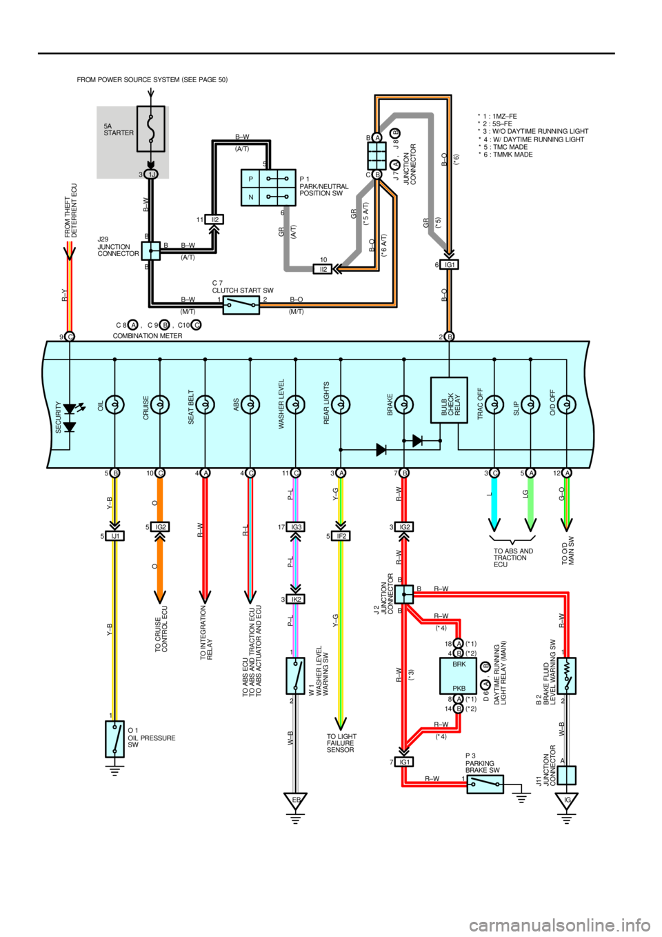
5A
STARTER FROM POWER SOURCE SYSTEM (
SEE PAGE 50)
1J 3
IJ1 5IF2 5 IG2 5IG317 IG23
IK2 3 C 9B 2
B 5C10 A4C4C11 A3B7C3A5A12
EB 2 1 II2 11A B
B C
IG1 6
11
IG1 7
12 1
IG
R±Y
B±W
GR
B±O Y±B Y±B
O O
R±W
R±L
P±L
Y±G P±L P±L W±B
Y±G
R±W R±W R±W
R±W W±B
B±W
B±WB±W
B±O
R±W
R±W R±W
R±W PARK /NEUTRAL
POSITION SW P 1
OIL PRESSURE
SW O 1
PARKING
BRAKE SW P 3 CLUTCH START SW C 7
WASHER LEVEL
WARNING SW W 1
JUNCTION
CONNECTOR J 2
BRAKE FLUID
LEVEL WARNING SW B 2
JUNCTION
CONNECTOR J11L
LG
G± O
B5
B B6
2B B
BFROM THEFT
DETERRENT ECU SECURITY
OIL
CRUISE
SEAT BELT
ABS
WASHER LEVEL
REAR LIGHTS
BRAKE
BULB
CHECK
RELAY
TRAC OFF
SLIP
O/D OFF
(
A/T)
(
M/T) JUNCTION
CONNE CTOR J29
(
M/T) (
A/T)
P
N
(
*5)
(
*6) (
*3)
(
*4)
(
*4)PKB BRK
A
TO CRUISE
CONTROL ECU
TO INTEGRATION
RELAY
TO ABS ECU
TO ABS AND TRACTION ECU
TO ABS ACTUATOR AND ECU
TO LI GHT
FAI LURE
SENSORTO ABS AND
TRACTION
ECU
GR
(
A/T)
II2 10
GR
B±O
B±O(
*5 A/T)
(
*6 A/T)
TO O/D
MAIN SWJ 7
JUNCTION
CONNECTORB A, J 8
C 8
COMBINA TION METERB A, C 9 C, C10* 1 : 1 MZ± FE
* 2 : 5S±FE
* 3 : W/O DAYTIME RUNNING LIGHT
* 4 : W/ DAYTIME RUNNING LIGHT
* 5 : TMC MADE
* 6 : TMMK MADE
B 4(
*2) A 18(
*1)
A 8(
*1)
B 14(
*2)
B D 6 , A
DAY TIME RUNNING
LIGHT RELAY (
MAIN)
Page 1431 of 4770
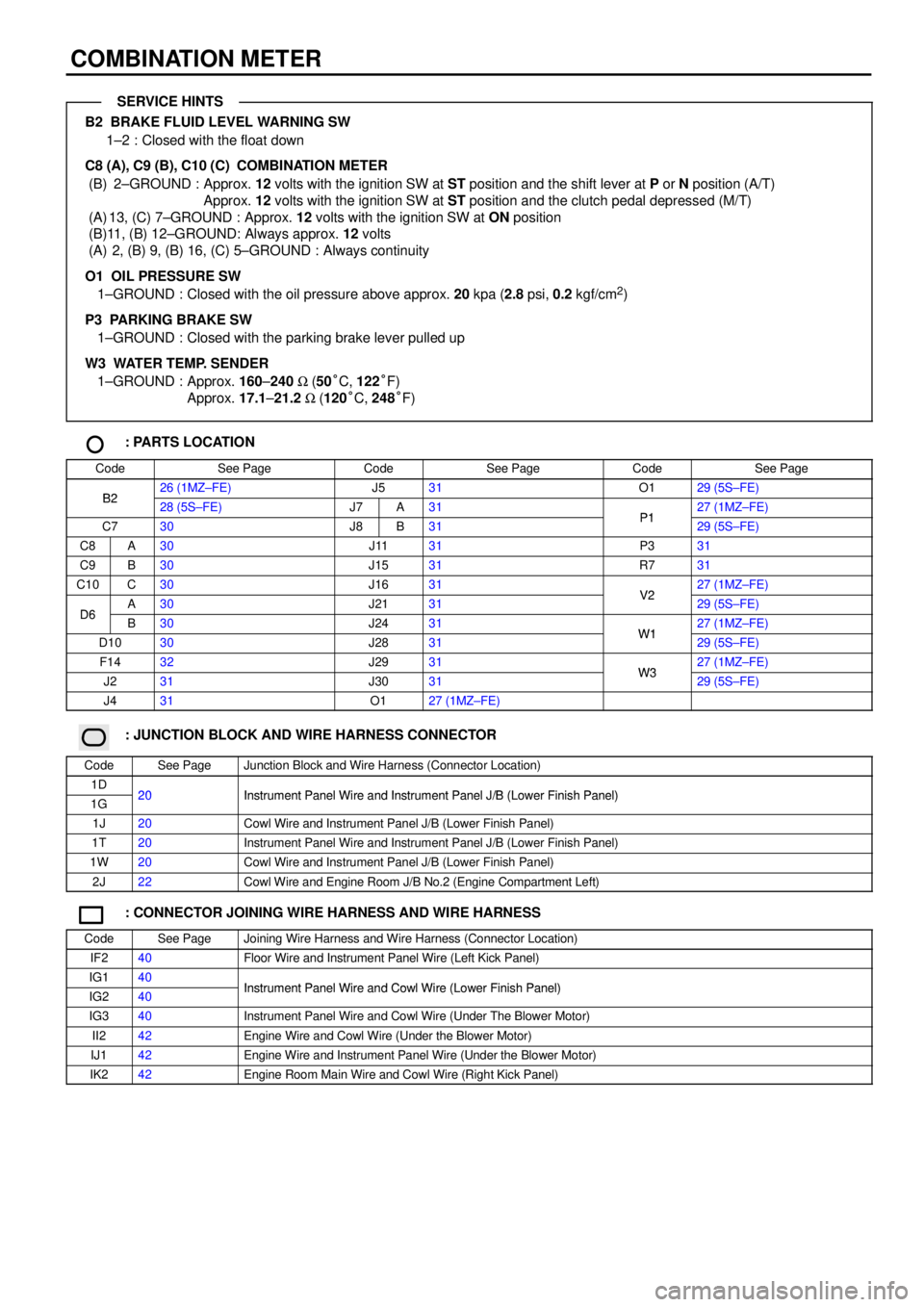
COMBINATION METER
B2 BRAKE FLUID LEVEL WARNING SW
1±2 : Closed with the float down
C8 (A), C9 (B), C10 (C)
COMBINATION METER
(B) 2±GROUND : Approx. 12 volts with the ignition SW at ST position and the shift lever at P or N position (A/T)
Approx. 12 volts with the ignition SW at ST position and the clutch pedal depressed (M/T)
(A) 13, (C) 7±GROUND : Approx. 12 volts with the ignition SW at ON position
(B)11, (B) 12±GROUND: Always approx. 12 volts
(A) 2, (B) 9, (B) 16, (C) 5±GROUND : Always continuity
O1 OIL PRESSURE SW
1±GROUND : Closed with the oil pressure above approx. 20 kpa (2.8 psi, 0.2 kgf/cm
2)
P3 PARKING BRAKE SW
1±GROUND : Closed with the parking brake lever pulled up
W3 WATER TEMP. SENDER
1±GROUND : Approx. 160±240 W (50°C, 122°F)
Approx. 17.1±21.2 W (120°C, 248°F)
: PARTS LOCATION
CodeSee PageCodeSee PageCodeSee Page
B226 (1MZ±FE)J531O129 (5S±FE)B228 (5S±FE)J7A31P127 (1MZ±FE)
C730J8B31P129 (5S±FE)
C8A30J1131P331
C9B30J1531R731
C10C30J1631V227 (1MZ±FE)
D6A30J2131V229 (5S±FE)D6B30J2431W127 (1MZ±FE)
D1030J2831W129 (5S±FE)
F1432J2931W327 (1MZ±FE)
J231J3031W329 (5S±FE)
J431O127 (1MZ±FE)
: JUNCTION BLOCK AND WIRE HARNESS CONNECTOR
CodeSee PageJunction Block and Wire Harness (Connector Location)
1D20Instrument Panel Wire and Instrument Panel J/B (Lower Finish Panel)1G20Instrument Panel Wire and Instrument Panel J/B (Lower Finish Panel)
1J20Cowl Wire and Instrument Panel J/B (Lower Finish Panel)
1T20Instrument Panel Wire and Instrument Panel J/B (Lower Finish Panel)
1W20Cowl Wire and Instrument Panel J/B (Lower Finish Panel)
2J22Cowl Wire and Engine Room J/B No.2 (Engine Compartment Left)
: CONNECTOR JOINING WIRE HARNESS AND WIRE HARNESS
CodeSee PageJoining Wire Harness and Wire Harness (Connector Location)
IF240Floor Wire and Instrument Panel Wire (Left Kick Panel)
IG140Instrument Panel Wire and Cowl Wire (Lower Finish Panel)IG240Instrument Panel Wire and Cowl Wire (Lower Finish Panel)
IG340Instrument Panel Wire and Cowl Wire (Under The Blower Motor)
II242Engine Wire and Cowl Wire (Under the Blower Motor)
IJ142Engine Wire and Instrument Panel Wire (Under the Blower Motor)
IK242Engine Room Main Wire and Cowl Wire (Right Kick Panel)
SERVICE HINTS