2000 TOYOTA CAMRY oil
[x] Cancel search: oilPage 1436 of 4770

FAN MOTOR OPERATION (1MZ±FE)
With the ignition SW turned on, the current through the ECU±IG fuse flows to the FAN NO.1 relay (Coil side), FAN NO.2 relay
(Coil side) and FAN NO.3 relay (Coil side). Furthermore, the current through the FAN NO.1 relay (Coil side) or the FAN NO.2
relay (Coil side) flows to TERMINAL 3 of the A/C single pressure SW to TERMINAL 2 to TERMINAL 2 of the water temp. SW
No.1 to TERMINAL 1 to GROUND, causing the FAN NO.1 relay to turn off and the FAN NO.2 relay to turn on.
1. LOW SPEED OPERATION
Only when the A/C system is activated or the water temp. SW No.2 is turned on, the A/C condenser fan motor and the
radiator fan motor rotates at low speed.
When the A/C system is activated, the current from ECU±IG fuse flows to the FAN NO.3 relay (Coil side) to TERMINAL 1 of
the diode (A/C) to TERMINAL 2 to TERMINAL (A)12 of the A/C amplifier (Manual A/C) or (B) 2 of the A/C control assembly
(Automatic A/C) causing the FAN NO.3 relay to turn on. As a result, the current through the CDS fuse flows to TERMINAL 2
of the A/C condenser fan motor to TERMINAL 1 to TERMINAL 3 of the FAN NO.2 relay to TERMINAL 5 to TERMINAL 5 of
the FAN NO.3 relay to TERMINAL 3 to TERMINAL 2 of the radiator fan motor to TERMINAL 1 to GROUND. As this flowing in
series for the motors, the motors rotate at low speed.
When the water temp. SW No.2 is turned on, the current from ECU±IG fuse flows to the FAN NO.3 relay (Coil side) to
TERMINAL 1 of the water temp. SW No.2 to GROUND, causing the FAN NO.3 relay to turn on. As a result, the current
through the CDS fuse flows the same route as above, rotating the motors at low speed.
2. HIGH SPEED OPERATION
Only when the A/C single pressure SW is turned off or the water temp. SW No.1 is turned off, the A/C condenser fan motor
and the radiator fan motor rotate at high speed.
When the A/C single pressure SW is turned off, the current from the RDI fuse flows to the FAN NO.1 relay (Point side) to
TERMINAL 2 of the radiator fan motor to TERMINAL 1 to GROUND. At the same time, the current from the CDS fuse flows
to TERMINAL 2 of the A/C condenser fan motor to TERMINAL 1 to TERMINAL 3 of the FAN NO.2 relay to TERMINAL 4 to
GROUND.
As the current flowing in parallel for the motors as above, the motors rotate at high speed.
FAN MOTOR OPERATION (5S±FE)
With the ignition SW turned on, the current through the ECU±IG fuse flows to the FAN NO.1 relay (Coil side), FAN NO.2 relay
(Coil side). furthermore, the current through the FAN NO.1 relay (Coil side) or the FAN NO.2 relay (Coil side) flows to
TERMINAL 3 of the A/C single pressure SW to TERMINAL 2 to TERMINAL 2 of the water temp. SW No.1 to TERMINAL 1 to
GROUND, causing the FAN NO.1 relay to turn off and the FAN NO.2 relay to turn on.
1. LOW SPEED OPERATION
When the ignition SW is turned on and the A/C system is activated, the A/C condenser fan motor and the radiator fan motor
rotates at low speed.
When the A/C system is activated, the current from MG CLT relay flows to the FAN NO.3 relay (Coil side) to GROUND,
causing the FAN NO.3 relay to turn on. As a result, the current through the CDS fuse flows to TERMINAL 2 of the A/C
condenser fan motor to TERMINAL 1 to TERMINAL 3 of the FAN NO.2 relay to TERMINAL 5 to TERMINAL 5 of the FAN
NO.3 relay to TERMINAL 3 to TERMINAL 2 of the radiator fan motor to TERMINAL 1 to GROUND. As this flowing in series
for the motors, the motors rotate at low speed.
2. HIGH SPEED OPERATION
Only when the A/C single pressure SW is turned off or the water temp. SW No.1 is turned off, the A/C condenser fan motor
and the radiator fan motor rotate at high speed.
When the A/C single pressure SW is turned off, the current from the RDI fuse flows to the FAN NO.1 relay (Point side) to
TERMINAL 2 of the radiator fan motor to TERMINAL 1 to GROUND. At the same time, the current from the CDS fuse flows
to TERMINAL 2 of the A/C condenser fan motor to TERMINAL 1 to TERMINAL 3 of the FAN NO.2 relay to TERMINAL 4 to
GROUND.
As the current flowing in parallel for the motors as above, the motors rotate at high speed.
A3 A/C SINGLE PRESSURE SW
3±2 : Open above approx. 15.5 kgf/cm2
(224 psi, 1520 kpa)
Closed below approx. 12.5 kgf/cm2 (181 psi, 1225 kpa)
W4 WATER TEMP. SW NO.1
2±1 : Open above approx. 95°C (203° F)
W5 WATER TEMP. SW NO.2 (1MZ±FE)
1±GROUND : Closed above approx. 90°C (194°F)
SYSTEM OUTLINE
SERVICE HINTS
Page 1450 of 4770
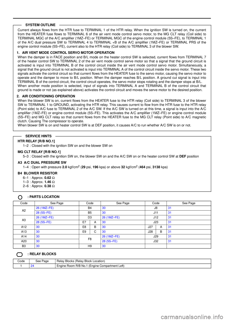
Current always flows from the HTR fuse to TERMINAL 1 of the HTR relay. When the ignition SW is turned on, the current
from the HEATER fuse flows to TERMINAL 6 of the air vent mode control servo motor, to the MG CLT relay (Coil side) to
TERMINAL MGC of the A/C amplifier (1MZ±FE) or TERMINAL MGC of the engine control module (5S±FE), to TERMINAL 1
of the A/C dual pressure SW to TERMINAL 4 to TERMINAL +B of the A/C amplifier (1MZ±FE) or TERMINAL PRS of the
engine control module (5S±FE), current also to the HTR relay (Coil side) to TERMINAL 3 of the blower SW.
1. AIR VENT MODE CONTROL SERVO MOTOR OPERATION
When the damper is in FACE position and B/L mode on the heater control SW is selected, current flows from TERMINAL 7
of the heater control SW to TERMINAL 2 of the air vent mode control serve motor so that a signal that the ground circuit is
activated is input into TERMINAL B of the control circuit inside the air vent mode control servo motor. Simultaneously, a
signal that the ground circuit is not activated is input into TERMINAL A of the control circuit inside the servo motor. These two
signals activate the control circuit so that current flows from the HEATER fuse to the servo motor, causing the servo motor to
operate and the damper to move to B/L position. When the damper reaches B/L position. A ground cut signal is input into
TERMINAL B of the control circuit, the control circuit operates, the servo motor stops rotating and the damper stops at B/L.
When another mode position is selected, input of signals into TERMINAL A and TERMINAL B of the control circuit that
ground is made or not (as explained above) activates the control circuit and moves the serve motor to the desired position.
2. AIR CONDITIONING OPERATION
When the blower SW is on, current flows from the HEATER fuse to the HTR relay (Coil side) to TERMINAL 3 of the blower
SW to TERMINAL 1 to GROUND, activating the HTR relay. This causes current to flow from the HTR fuse to the HTR relay
(Point side) to A/C fuse to TERMINAL 2 of the A/C SW. If the A/C SW is turned on at this time, a signal is input into the A/C
amplifier (1MZ±FE) or engine control module (5S±FE). This activates the A/C amplifier (1MZ±FE) or engine control module
(5S±FE) and MG CLT relay so that current flows from the HEATER fuse to the MG CLT relay (Point side) to A/C magnetic
clutch. Causing The compressor to operate.
When blower SW is on and heater control SW is at DEF position, it causes A/C to run whether A/C SW is on or not.
HTR RELAY [R/B NO.1]
1±2 : Closed with the ignition SW on and the blower SW on
MG CLT RELAY [R/B NO.1]
5±3 : Closed with the ignition SW on, the blower SW on and the A/C SW on or the heater control SW at DEF position
A3 A/C DUAL PRESSURE SW
1±4 : Open with pressure 2.0 kgf/cm
2 (29 psi, 196 kpa) or above 32 kgf/cm2 (464 psi, 3138 kpa)
B4
BLOWER RESISTOR
6±1 : Approx. 0.62 W
1±3 : Approx. 1.46 W
2±6 : Approx. 0.38 W
: PARTS LOCATION
CodeSee PageCodeSee PageCodeSee Page
A226 (1MZ±FE)B430J831A228 (5S±FE)B530J1131
A326 (1MZ±FE)D326 (1MZ±FE)J1231A328 (5S±FE)E7A30J2331
A1230E8B30J27A31
A1330E9C30J28B31
A1430F826 (1MZ±FE)J2931
A2030F828 (5S±FE)J3231
B330H930
: RELAY BLOCKS
CodeSee PageRelay Blocks (Relay Block Location)
124Engine Room R/B No.1 (Engine Compartment Left)
SYSTEM OUTLINE
SERVICE HINTS
Page 1454 of 4770
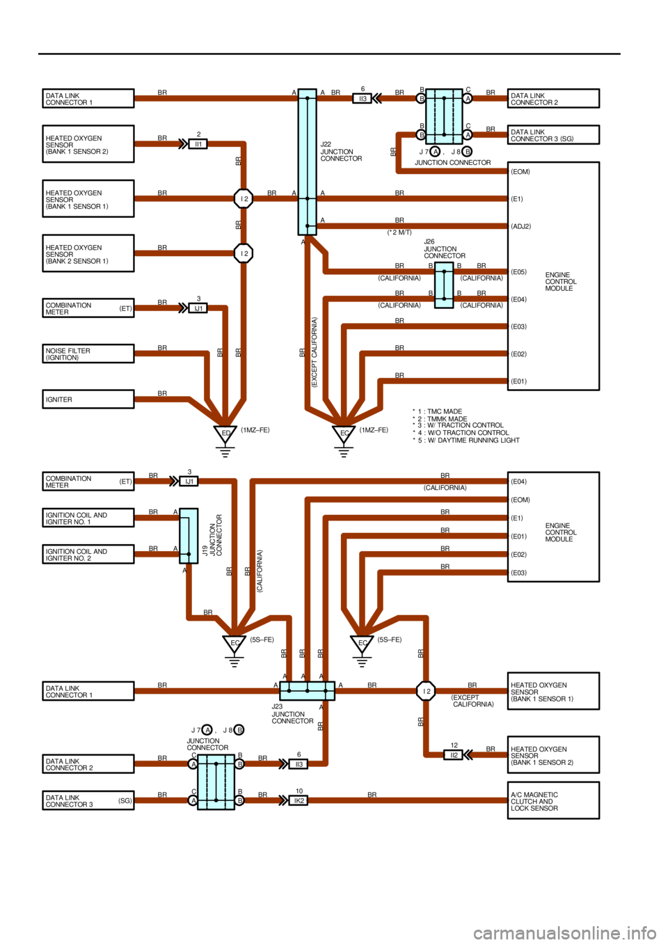
HEATED OXYGEN
SENSOR
(
BANK 1 SENSOR 2)
HEATED OXYGEN
SENSOR
(
BANK 1 SENSOR 1)
HEATED OXYGEN
SENSOR
(
BANK 2 SENSOR 1)
COMBINATION
METER
NOISE FILTER
(
IGNITION)
IGNITER DATA LINK
CONNECTOR 1DATA LINK
CONNE CTOR 2
DATA LINK
CONNE CTOR 3 (
SG)
(
E1)
(
ADJ2)
(
E03)
(
E02)
(
E01)
(
E04)
(
E1)
(
E01)
(
E02)
(
E03)
HEATED OXYGEN
SENSOR
(
BANK 1 SENSOR 1)
HEATED OXYGEN
SENSOR
(
BANK 1 SENSOR 2)
A/C MAGNETIC
CLUTCH AND
LOCK SENSOR COMBINATION
METER
IGNITION COIL AND
IGNITER NO. 1
IGNITION COIL AND
IGNITER NO. 2
DATA LINK
CONNECTOR 1
DATA LINK
CONNECTOR 2
DATA LINK
CONNECTOR 3ENGINE
CONTROL
MODULE
ED ECI 2
I 2 II12
IJ13II36
B B
A C
A C
(
1MZ± FE) (
1MZ± FE)A AA
A
A
A BR
BR
BR
BRBR
BR BR BR
BR
BR
BR
BR
BR
BR
BR
BRBR BR
BR
BRJUNCTION
CONNECTOR J22
BR
(
*2 M/T)
* 1 : TMC MADE
* 2 : TMMK MADE
* 3 : W/ TRACTION CONTROL
* 5 : W/ DAYTIME RUNNING LIGHT
ENGINE
CONTROL
MODULE IJ13
A
A
EC A
EC
I 2
II2 12
B B
B B A C
A CII36
IK210 AAA
A BR
BR
BR
BRBR
BR
BR
BR
BR
BR BR
BR
BR BR
BR BR BR BR
BR
BR BRBR BRBR
BR
(
EXCEPT
CALIFORNIA)
(
CALIFORNIA)
(
CALIFORNIA)
A (
5S±FE)(
5S±FE)
JUNCTION
CONNECTOR J19
JUNCTION
CONNECTOR J23 (
ET)
(
ET)
(
SG)B B
J 7
JUNCTION CONNECTORB A, J 8
BR
(
CALIFORNIA)
BR
(
CALIFORNIA) BR
(
CALIFORNIA)(
E05)
(
E04) J2 6
JUNCTION
CONNECTOR
(
EOM)
BR
A
J 7
JUNCTION
CONNECTORB A, J 8(
EOM)
BR
(
CALIFORNIA) BR
BR
B BB
B
* 4 : W/O TRACTION CONTROL
(
E XCEPT CALIFORNIA)
Page 1464 of 4770
J
1
234
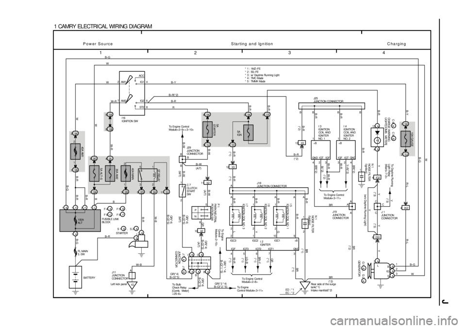
1 CAMRY ELECTRI CAL WI RI NG DI AGRAM
2ACC
IG1
IG2
ST2 AM1 4
6
8 7AM2
1B 51K 5
2 1
3 5
5A ALT±S30A AM2 40A MAIN
2L 4 2C 3
2A 12B32D52K92J11
1F 2F 1B
1A1K 2
1B 1
40A AM1
1A
1
B
IG
5A
ST ARTER
5A
IGN 1K 41K3
1J 31C8
65
P
N
10 II2
CB
BA BA
B±W
GR (
A/T)
Left kick panel12 I I3
2 1 1C
1A
L
B
A
A B
IG
S 4B 13 A1K 1
1J 2
4IG2
6 EB14IK2 1T 8
4567 32 2 2 AAAAA
C 423 324 BB B
9 10 1 21 1
A
1 1 1 R B±R B±Y W W B±G
B±O(
*5) B
B± R
B± R
B± RB±R B± R
G
Y
LW±RLG±B
BR±YGRBR BR
W± RW± R
W
WB±RB±R
B±RB
B±GB± G B± R W± B GR(
*4)
B± O(
*5) B±WYY Y Y
BR(
*2)
Y±R(
*2)
W± R
W± R
B(
*2)
BR(
*2)
B±R B±R
B±R B±RB±R B±Y R±L R±LB±GW
B±G
W
B±R B±R
(
M/T) (
*1)(
*1)
I16
IGNITION SW
I 7
IGNITION COIL NO. 3 I 6
IGNITION COIL NO. 2 I 5
IGNITION COIL NO. 1
ST REL AYP 1
PARK/ NEUTRAL
POSITI ON SW
J18
JUNCTI ON CONNECTOR
100A
ALTFUSI BLE LI NK
BL OCK
FL MAIN
3. 0W
BATTERYST ARTER
JUNCTION
CONNECTOR To En gi n e
Co nt r ol
Module< 2±10>
To Engine Contr ol
Module< 2±8>C
C
Y
N 1
NOI SE FI LTER
(
I gnit ion)
J25
JUNCTI ON CONNECTOR
I 3
IGNITION
COI L A ND
IGNITER
NO. 1I 4
IGNITION
COIL AND
IGNITER
NO. 2 * 1 : 1MZ±FE
* 2 : 5S±FE
To Dayt ime Running
Light Relay
(
Main)
< 7±2>
GENERATOR
J 1
JUNCTION
CONNECTOR
CHARGE WARNING
LIGHT[ COMB. METER]
1 2
IGC3 IGC2 IGC1 +B
I GF IGT3 I GT2 I GT1 GND* 3 : w/ Dayt ime Running Light
(
*3)
W± RBR
A AA
BR
BR To Engine Control
Module< 3±11>
J19
JUNCTI ON
CONNE CTOR
I 2
IGNITER ,
A
To Eng i ne
Control Module< 3±11>
10A GAUGE
B±R
BR
(
*1)
(
*1)
(
*2) J11
JUNCTION
CONNECTORGR(
*4)
BA
To Bul b
Ch ec k Rel a y
[Comb. Meter]
< 25±6>2 1
11 II2 B
B B
B±W
(
A/T)
B±WJ29
JUNCTION
CONNECTOR13 II3
B±R
(
*2)
1B±RB
N 1
NOISE FILTER
(
Ignition)(
*3)(
*3)
Y
(
w/o Day time Running Light)
* 4 : TMC Made
* 5 : TMMK Made
GR(
*4)
B± O(
*5) GR(
*4)
B±O(
*5)
B±W
C 7
CLUTCH
ST ART
SW
GR(
*1 *4)
B±O(
*1 *5)
GR(
*2 *4)
B±O(
*2 *5)
GR(
*4)
B±O(
*5)
1
3 2
(
M/ T)
Rear side of the s urge
tank(
*1)
Intake manifold(
*2) ED : * 1
EC : * 2 B±R(
*2)
GN D I GT I GF I GF I GT GN D+B +B
Power Source Starting and Ignition Charging
B±R
(
*2)
W± BTo Engine Cont rol
Module< 2±9> < 3±10>
(
A/T)
, F 5 F 4 A B
, F 9 F 6 C F
, S 2 S 1 B A
B J 7 J 8A, B C 8 C 9A,
A G 1 G 2B,
1 2
CB
(
*1)
(
*1)
(
*1)
(
*1) (
*2)(
*2)
Page 1470 of 4770
J
5
678
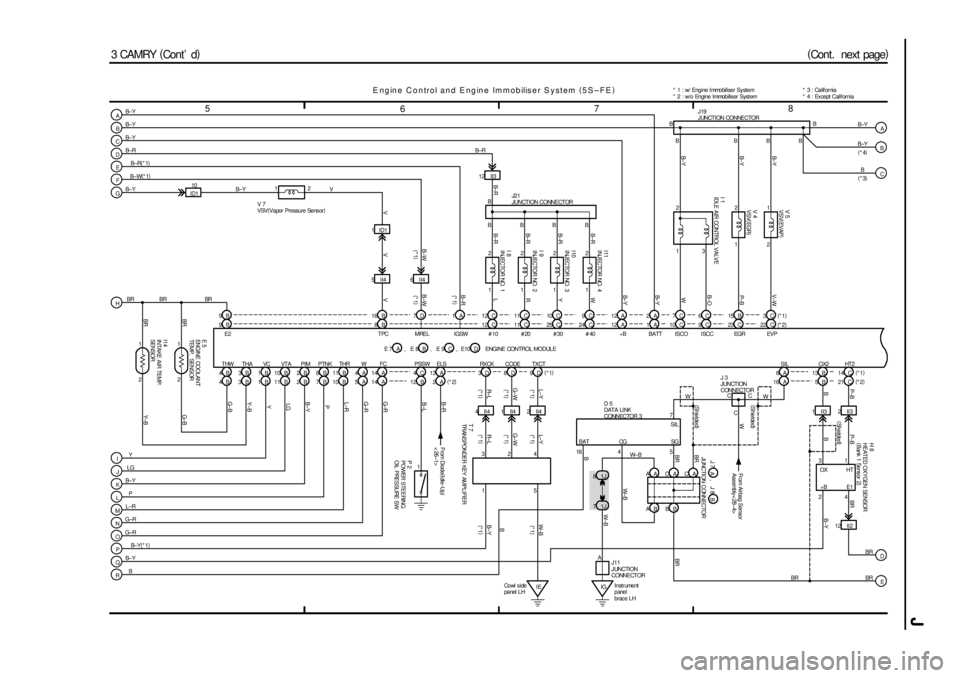
3 CAMRY (
Cont ' d)A
B
C
R Q O N ML KJI12 C
#10 #20
THW
B 411 C
R
G±B
#30
THA
B 325 CY
Y±B
#40
VC
B 124 CW
Y
+B
VT A
B 1112 AB± Y
LG
BATT
PIM
B 21AB± Y
B±Y
ISCO
PTNK
B 710 CW
P
ISCC
THR
B 109CB±O
L±R
EGR
W
A 523 CP± B
G±R
FC
A 14G±R
PSSW
B 12B±L
ELS
A 2B±R
Y
LG
B±Y
P
L±R
G±R
G±R
B±Y
B1 2
3
I 1
IDLE AIR CONTROL VALVE
1 2
EVP 22 C
V±W2 1
TPC 8B
V V 4
VSV(
EGR) V 5
VSV(
EVAP)
V 7
VSV(
Vapor Pressure Sens or)B
BBBBB
B± Y B± Y B± Y
V
1
From Diode(
Idle±Up)
< 26±1>
B±Y B±Y B±Y
B±Y
B±Y
P 2
POWER STEERING
OIL PRESSURE SW
(
*4) J19
JUNCTION CONNECTOR
E ngine Control and Engine Immobiliser System (
5S±FE)
(
Cont. next page)
ENGI NE CONTROL MODULE1 2
I11
INJECTOR NO. 4
1 2
I10
INJECTOR NO. 3
1 2
I 9
INJECTOR NO. 2
1 2
I 8
INJECTOR NO. 1
B B
BBB J21
JUNCTION CONNECTOR
B±R
B±R
B±R
B±R L
B±R
D
12 II3
B± R
E
F
IGSW 1A
B±R
MREL 7DB±W
6II4
BRE 5
ENGINE COOLANT
TEMP. SENSOR
I14
INTAKE AIR TEMP.
SENSOR
BR BR
BR
1
21
2E2 9BY± B G± B
HA
B
C B
5II4 1ID1 12
G
PID110 B±R(
*1)
B±W(
*1)
B±Y B±Y
9B12C 11C 10C 9C 12A 2A 7C 6C 15B 3C
4B 3B 1B 10B 2B 8B 11B 4A 14A 4C 13A 3D 8D 9D
4 II4 1 II4 2 II4
IE Co wl s i de
panel LH1II3
W± B
14 CHT 2 OX2
B 13 6ASIL
SIL
JUNCTION CONNECTOR
A C A ASG
B BBR
B A CG
W± B
71J
BR 81J7
IG5 D 5
DATA LI NK
CONNECTOR 3
42II3
(
Shielded)
3
12 II2 241BBR P± B P±B
BB±Y
A
J11
JUNCTION
CONNECTORW± B BR
HT
E1 OX
+B
D
E
T 7
TRANSPONDER KEY AMPLIFIER
Instrument
panel
brac e LH* 1 : w/ Engine Immobiliser System
* 2 : w/o Engine Immobiliser System
W±B
(
*1)
R± L G±WL±Y
R±L G±WL±Y
B±YB
(
*1)(
*1) (
*1) (
*1) (
*1)(
*1)
(
*1)
324
1A C BAT
16
5
(
Shielded) (
Shielded)
J 3
JUNCTION
CONNECTOR
WW B±R
B±W
V
V
16 B BR(
*3)
(
*2) (
*1)
B± Y(
*1)(
*2)(
*1)
BR
BR CC
BR
21 C B 5 16 A(
*2) (
*1)
(
*1)(
*1) (
*1)B H 8
HEATED OXYGEN SENSOR
(
Bank 1 Sens or 2)
RX CK CODE TX CT
B J 7 J 8A,
, E 8 E 7 A B , E 9 C , E10 D
C
W
From Airbag Sensor
Assembly< 28±4>
* 3 : California
* 4 : Ex cept Calif ornia
Page 1471 of 4770

J OVERALL ELECTRICAL WIRING DIAGRAM
9
1011 12
3 CAMRY (
Cont ' d)
ECIntake
man i f ol d ST P 4A
LOCK IN18 C
PRS 13 A
G±WW± LG
MGC 21 AL±YA/ C SW 10 AR±B
LOCK 15 AR± W
NS W 22 AB±W
STA 11 A
GR(
*5)
B±O(
*6)
IGT1 20 CB
IGF 3CW±R
IGT2 19 CY±R
10 II3
W± L
TE1 15 B From Ignition Coil
and Igniter
No. 1, No. 2< 1±3> < 1±4>
12 DNE+
1 2
C 2
CRANKSHAFT
POSI TI ON SENSOR
1 2C 1
CAMSHAFT
POSI TI ON SENSOR6DNE±
11 DG+
12 BKNK
25 CE03
26 CE02
13 CE01
8ASPD
7A15 CE04
To Speedometer
[Comb. Meter]
< 25±8> L
EC Intake
ma ni f o ldBR
B±YBR BR BR(
*4)
BR BR
BR
BR
BR
B±RBRL B±W W
1
(
Shielded) (
Shielded) (
Shielded)BR
BR
BRBR
BR A
A
AA
A
A
AJ23
JUNCTION
CONNECTOR
BR
V± W BR BR
BR
(
*3)
(
*4) TE1 E1+B
L±W
From St op Light
SW< 11±4> To A/ C Magnetic
Clutc h and Loc k
Sens or < 27±4>From A/C Dual
Pressure SW< 27±4>Fr om MG CL T
Relay< 27±3>Fro m A/ C SW
< 27±4> Fro m A/ C SW
< 27±4> Fr om º STARTERº
Fuse< 1±2> From Park/Neut ral Position
SW(
A/ T)
or Clutc h Star t
SW(
M/ T)
< 1±2>12
83D 1
DATA LINK
CONNECTOR 1* 3 : Califor nia
* 4 : Exc ept Calif or nia * 2 : w/o Engine Immobiliser SystemBR BR
24 CE1
BR
(
*3)
ENGINE CONTROL MODULE
A
6II3
Engine Control and Engine Immobiliser System (
5S±FE)BR
BR
BR
BR
G L(
*5)
W(
*6) W
BR
A1 1
AI R F UEL
RA TI O SE NSORHTAF 2C
AF± 14 B
AF + 6B
OX1 6B
HT1 8C 14 23
31 24
H 3
HEAT ED OXYGEN SENSOR
(
Bank 1 Sens or 1)
(
*3) B±W(
*5)
O (
*6)
(
*3) (
*3) (
Shielded) (
Shielded) (
*4) L±Y
(
*4)
HTE1
OX+B
HT AF±+B AF+ A
B
C
D
EB B±Y B±Y
(
*4)
(
*3)
B±Y
(
*4)
1DIMLD
4DKSW
3II4
4IG3 8IG3
To Theft
Det er rent
System< 15±3>To Un l oc k
War ning SW
< 21±3>R±YL±B
R±YL±B
R± YL±B
BR(
*2) 9A 19C 19A 21A 10A 20A 22A 11A 23C 17C 22C 7B 2C14B6B 5B1C(
*1)
9A 8A 4C 17C 5C 13B 15C 14C2DEOM
BR
A16 B 26 C 13 C(
*2) (
*1)
(
*2)* 5 : TMC Made
* 6 : TMMK Made
(
*4)
FA
To Tac hometer
[Comb. Meter]
< 25±5>FA
B±O B±OTACH
JUNCTION
CONNECTORJ27 A
* 1 : w/ Engine Immobiliser System
, E 8 E 7 A B , E 9 C , E10 D
9II4
(
A/T)
K 1
KNOCK SENSOR 1
Page 1496 of 4770
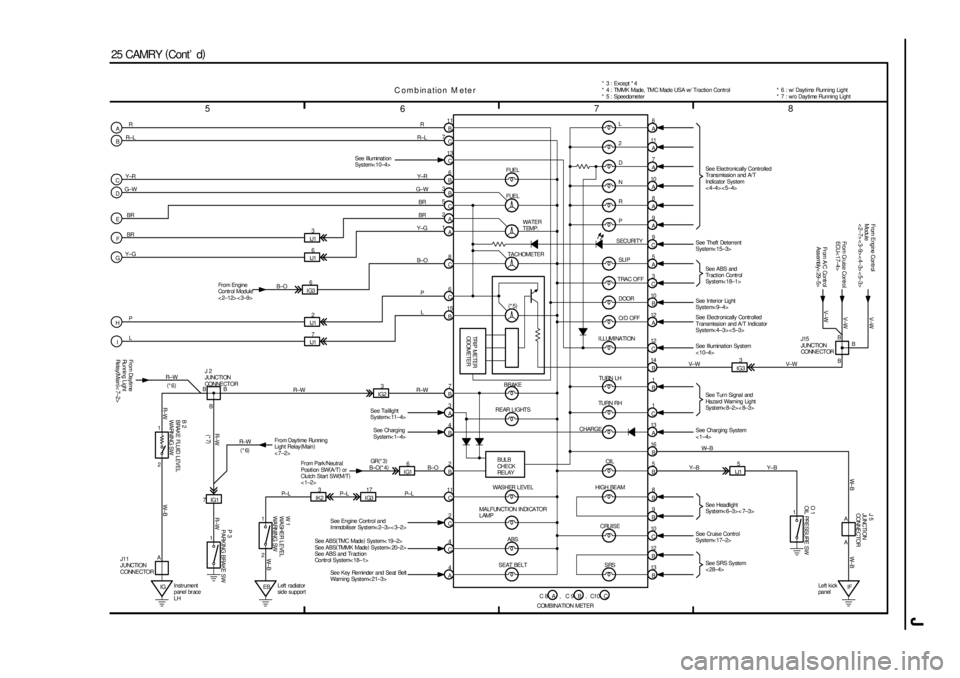
J
5
678
25 CAMRY (
Cont' d)
11
B
7
C
13
C
6
B
3
B
5
C
2
A
1
A R
R±L
Y±R
G±W
BR
BR
IJ13
IJ16
IJ12
IJ178
C
6
C
15
B Y±G
P
LR
R±L
Y± R
G±W
BR
BR
Y±G
B±O
P
L
4
A4
C2
C 11
C2
B4
B3
A7
B
IG317
IK23
2 1
EBLeft radiat or
side support IGInstrument
panel br ace
LH 2 1IG23
IG16
7IG16
A
11
A
7
A
8
A 10
A
9
A
9
C
5
A
3
C
10
B
12
A
13
B 12
B 10
C9
B8
B5
B 16
B 13
A1
C1
B 14
B 12
C L
2
D
N
R
P
SLI P
TRAC OFF
DOOR
O/D OFF See Illuminat ion
System< 10±4>
A
R±W R± W
W± B R±WW± B
R±W
R±W R±W
B±O
P± L P±L P± LB±O(
*4) R± W (
*6)
(
*7)J 2
JUNCTI ON
CONNE CT OR
Fro m Da yti me
Running Light
Re la y(
Main)
< 7±2>
B
BB
(
*6)
J11
JUNCTION
CONNECTOR
B 2
BRAKE FLUID LEVEL
WARNING SWP 3
PARKING BRAKE SW W 1
WASHER L EVEL
WARNING SW
From Day time Running
Light Relay(
Main)
< 7±2>
Fr om Park /Neutral
Pos it ion SW(
A/T)
or
Clutch Start SW(
M/T)
<1±2>GR(
*3)
See Key Reminder and Seat Belt
Warning System< 21±3> See ABS(
TMC Made)
System< 19±2>
See ABS(
TMMK Made)
System< 20±2>
See ABS and Tr act ion
Control System< 18±1>See Engine Cont rol and
Immobiliser System< 2±3> < 3±2>See Charging
System< 1±4> See Taillight
System< 11±4>
SRS CRUISE HIGH BEAMOIL
SEAT BELTABS MA LF UNCT I ON I NDI CA TOR
LAMPWASHER LEVELBULB
CHE CK
RE L AY REAR LIGHTSBRAKE
CHARGETURN RHTURN LH ILLUMINATION
TRIP METER
ODOMETER
(
*5) TACHOMETERWATER
TEMP. FUEL
FUEL
SECURI TYSee Electronically Controlled
Transmission and A/T
Indicator System
<4±4><5±4>
See ABS and
Tr act ion Contr ol
Sy st em< 18±1>
See Tur n Signal and
Hazard Warning Light
Sy st em< 8±2> < 8±3>
See Headlight
Sy st em< 6±3> < 7±3>
Se e SRS Sy st e m
< 28±4> See Theft Deterrent
System< 15±3>
See Interior Light
System< 9±4>
See Electronically Controlled
Transmiss ion and A/T Indicator
System< 4±3> < 5±3>
See Illumination Sy st em
< 10±4>
IG33
V± W V± W
V±W V±WB B
B J15
JUNCTION
CONNE CT ORFrom Cruise Control
ECU< 17±4> From Engine Contr ol
Module
< 2±7> < 3±9> < 4±3> < 5±3>
IJ15
1
See Cruise Control
System< 17±2> Y±B Y±B
IF Left kick
panel
O 1
OIL PRESSURE SWJ 5
JUNCTI ON
CONNE CTOR
W± B W± B
A A See Char ging Sys tem
< 1±4> A
B
C
D
E
F
G
H
I* 4 : TMMK Made, TMC Made USA w/ Traction Control
* 5 : Speedometer * 3 : Except * 4
W± B IG36
1
Combination M eter
B±O From Engine
Control Module
< 2±12> < 3±9>
C 8 C 9,
COMBINATION METERABC10, C* 6 : w/ Daytime Running Light
* 7 : w/o Day time Running Light
Fr om A/C Contr ol
Assembly< 29±5>V±W
Page 1512 of 4770

L
CodePart Name Part NumberCodePart Name Part Number
D18Door Lock Control SW RH (TMC Made)90980±11326D18Door Lock Control SW RH (TMMK Made)90980±10797
D19Door Lock Motor and Door Unlock
Detection SW Front LH
D20Door Lock Motor and Door Unlock
Detection SW Front RH
90980±11150
D21Door Lock Motor and Door Unlock
Detection SW Rear LH90980±11 150
D22Door Lock Motor and Door Unlock
Detection SW Rear RH
E 1EGR Gas Temp. Sensor90980±10899
E 2EGR Valve Position Sensor90980±11143
E3
Electronically Controlled Transmission
Solenoid (1MZ±FE)90980±10854
E 3Electronically Controlled Transmission
Solenoid (5S±FE)90980±11156
E 4Electronically Controlled Transmission
Solenoid90980±11143
E 5Engine Coolant Temp. Sensor90980±10737
E 6Engine Hood Courtesy SW90980±11189
E7Engine Control Module (1MZ±FE)90980±11638E 7Engine Control Module (5S±FE)90980±11392
E8Engine Control Module (1MZ±FE)90980±11637E 8Engine Control Module (5S±FE)90980±11391
E9Engine Control Module (1MZ±FE)90980±11586E 9Engine Control Module (5S±FE)90980±11390
E10Engine Control Module (1MZ±FE)90980±11476E10Engine Control Module (5S±FE)90980±11408
E11Engine Control Module90980±11421
F 1Front Turn Signal Light and Parking Light
LH
90980±11020
F 2Front Turn Signal Light and Parking Light
RH90980±11020
F 3Front Wiper Motor90980±11599
F 4Fusible Link Block
F 5Fusible Link Block
F 6Fusible Link Block±
F 7Fusible Link Block
F 8Fusible Link Block
F 9Fusible Link Block90980±11579
F10Front Door Speaker LH90980±10825F11Front Door Speaker RH90980±10825
F12Front Tweeter (Speaker) LH90980±10916F13Front Tweeter (Speaker) RH90980±10916
F14Fuel Pump and Sender90980±11077
G 1Generator90980±09213
G 2Generator90980±11349
G 3Glove Box Light and SW90980±11098
H 1Headlight LH90980±11314H 2Headlight RH90980±11314
H 3Heated Oxygen Sensor (Bank 1 Sensor 1)90980±11028H 4Heated Oxygen Sensor (Bank 2 Sensor 1)90980±11028
H 5Horn (High)90980±10619H 6Horn (Low)90980±10619
H 7Hazard SW90980±10801
H 8Heated Oxygen Sensor (Bank 1 Sensor 2)90980±11028
H 9Heater Control SW90980±10799
H10High Mounted Stop Light90980±11148
I 1Idle Air Control Valve90980±11145
I 2Igniter90980±11653
I 3Ignition Coil and Igniter No.190980±11150I 4Ignition Coil and Igniter No.290980±11 150
I 5Ignition Coil No.1
I 6Ignition Coil No.290980±11246
I 7Ignition Coil No.3
I 8Injector No.1
I 9Injector No.2
I10Injector No.390980±11153I11Injector No.490980±11 153
I12Injector No.5
I13Injector No.6
I14Intake Air Temp. Sensor90980±11163
I15Ignition Key Cylinder Light90980±10906
I16Ignition SW90980±11615
I17Integration Relay90980±11107
I18Integration Relay (w/ Theft Deterrent)90980±11058I18Integration Relay (w/o Theft Deterrent)90980±11542
I19Interior Light90980±10121
J 1Junction Connector90980±11542
J 2Junction Connector90980±10803
J 3Junction Connector90980±11542
J 4Junction Connector90980±10803
J 5Junction Connector90980±11542
J 6Junction Connector90980±11502
J 7Junction Connector
J 8Junction Connector90980±11661J 9Junction Connector90980±11661
J10Junction Connector
J11Junction Connector90980±10976
J12Junction Connector90980±10803
J13Junction Connector90980±11661J14Junction Connector90980±11661