Page 3210 of 4770

H02289
2 Airbag Sensor
Assembly
237
B±Y
12 IG2
C18LG
AB10A
ECU±B
Short Pin
W±R
1W Engine Room J/B No.2
11 B
II3 A
A 3
LG
5DLC1 1 Battery
4 J3 Junction
Connector
1G2J 2A B±G
F4 F6 FL MAINFusible Link Block
1
1
TCP±B7Instrument Panel J/B
C18
B A LAW±R
LG
13
TC B±Y (*1)
LG (*2)
LG±R (*3)
P±B (*4)
II3 LG±R11
B B
TC LG±R J3 Junction
Connector
19
DLC2 SRS Warning Light
*1: TMMK Made, 1MZ±FE
*2: Except *1
*3: TMC Made
*4: TMMK Made DI±790
± DIAGNOSTICSSUPPLEMENTAL RESTRAINT SYSTEM
1025 Author�: Date�:
SRS Warning Light Circuit Malfunction (Always lights up, when
ignition switch is in LOCK position.)
CIRCUIT DESCRIPTION
The SRS warning light is located on the combination meter.
When the SRS is normal, the SRS warning light lights up for approx. 6 seconds after the ignition switch is
turned from the LOCK position to ACC or ON position, and then turns off automatically.
If there is a malfunction in the SRS, the SRS warning light lights up to inform the driver of the abnormality.
When terminals Tc and E1 of the DLC1 are connected, the DTC is displayed by blinking the SRS warning
light.
WIRING DIAGRAM
DI1BO±08
Page 3212 of 4770

CIRCUIT DES")
N14677
Fuse
DI±792
± DIAGNOSTICSSUPPLEMENTAL RESTRAINT SYSTEM
1027 Author�: Date�:
SRS Warning Light Circuit Malfunction (Does not light up, when
ignition switch is turned to ACC or ON.)
CIRCUIT DESCRIPTION
The SRS warning light is located on the combination meter.
When the SRS is normal, the SRS warning light lights up for approx. 6 seconds after the ignition switch is
turned from LOCK position to ACC or ON position, and then turns off automatically.
If there is a malfunction in the SRS, the SRS warning light lights up to inform the driver of the abnormality.
When terminals Tc and E1 of the DLC1 are connected, the DTC is displayed by blinking the SRS warning
light.
WIRING DIAGRAM
See page DI±790.
INSPECTION PROCEDURE
1 Check ECU±B Fuse.
PREPARATION:
Remove ECU±B fuse.
CHECK:
Check continuity of ECU±B fuse.
OK:
Continuity
HINT:
�Fuse may be burnt out even if it appears to be OK during
visual inspection.
�If fuse is OK, install it.
NG Go to step 5.
OK
2 Prepare for inspection. (See step 1 on page DI±787)
DI1BP±08
Page 3216 of 4770
H08301
LG±R P±B
B
BJ3 Junction
ConnectorAirbag Sensor
Assembly
A2119
Tc
11
LG±R 11
Tc
E1DLC1
3 BR
A
J22 (1MZ±FE)
J23 (5S±FE)
Junction Connector
BR (*4)
ECEC BR A
Junction
Connector
6
J7B
J8 C
BR 3
E1Tc DLC2 LG±R (*1)
P±B (*2)
4
B II3
II3
BR
J22
Junction Connector
A A BR BR (*3)J26
Junction
ConnectorB
B
BR (*3)
*1: TMC Made
*2: TMMK Made
*3: California, 1MZ±FE
*4: Except California DI±796
± DIAGNOSTICSSUPPLEMENTAL RESTRAINT SYSTEM
1031 Author�: Date�:
Tc Terminal Circuit
CIRCUIT DESCRIPTION
By connecting terminals Tc and E1 of the DLC1 the airbag sensor assembly is set in the DTC output mode.
The DTCs are displayed by blinking the SRS warning light.
WIRING DIAGRAM
DI1BQ±08
Page 3230 of 4770
DI05R±03
I00225
Wireless Door Lock ECU
SHORT PIN
2A2J
DOME Engine Room J/B No.2
FL BLOCK
BatteryRR± J16J17
W±BJ5
A
GND B±G1
B12
FL MAIN
A
IF R
RED 1
1
1 1
8
12 R±YDIODE(DOME) 1W
1G
R8 Instrument
panel J/B F6
F4
J/C
W±B DI±810
± DIAGNOSTICSWIRELESS DOOR LOCK CONTROL SYSTEM
1045 Author�: Date�:
CIRCUIT INSPECTION
ECU Power Source Circuit
CIRCUIT DESCRIPTION
Battery positive voltage is always applied to the terminal +B of the wireless door lock ECU.
WIRING DIAGRAM
Page 3231 of 4770
N14677
AB0117
N14690
I00242
LOCK
E(±)
+B(+)
± DIAGNOSTICSWIRELESS DOOR LOCK CONTROL SYSTEM
DI±811
1046 Author�: Date�:
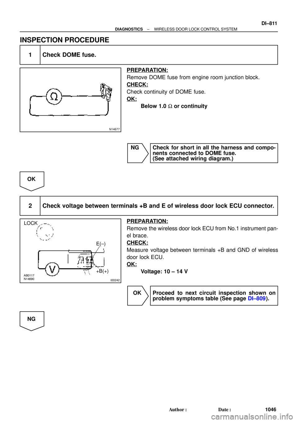
INSPECTION PROCEDURE
1 Check DOME fuse.
PREPARATION:
Remove DOME fuse from engine room junction block.
CHECK:
Check continuity of DOME fuse.
OK:
Below 1.0 W or continuity
NG Check for short in all the harness and compo-
nents connected to DOME fuse.
(See attached wiring diagram.)
OK
2 Check voltage between terminals +B and E of wireless door lock ECU connector.
PREPARATION:
Remove the wireless door lock ECU from No.1 instrument pan-
el brace.
CHECK:
Measure voltage between terminals +B and GND of wireless
door lock ECU.
OK:
Voltage: 10 ± 14 V
OK Proceed to next circuit inspection shown on
problem symptoms table (See page DI±809).
NG
Page 3233 of 4770

I08425
Theft Deterrent ECU
LSWD14
T4
LSWP
LSWR15
T4
16
T4Wireless Door
Lock ECU
W±B
*2
Door Unlock Detection
Switch Rear RH IE
Instrument Panel J/B J6
J/C
F
1111
L±RF
F
YL±R
LSWD
LSWP
LSWR W6
12
W6
13
W6 L±R L±R
IE1
Door Unlock Detection
Switch Rear LHDoor Unlock Detection
Switch Front RH Door Unlock
Detection Switch
Front LH
W±B*1W±B*1J38
20
W±B
J/C A
A
1
3 243 2
3 23 2 IE1
W±B3C
L±YE
J101V7
1GJ37 J/C
C
CY
Y Y11
IM1
1*1
4*2
W±B*1J39
J/CW±B*1
A
A
IM1 20
W±B
BN
IJ
IK L±Y J/C
D
J9
D J9 EJ10
L±Y L±Y L±Y
L±YL±Y L±Y
4
BO12
IF23
IN24
BP14
1
W±BW±B6
BP1
4 1
W±B
W±B6
BO1J40
J/CBL
4*1
1*2
*1: TMC Made
*2: TMMK Made W±BW±B
*2
± DIAGNOSTICSWIRELESS DOOR LOCK CONTROL SYSTEM
DI±813
1048 Author�: Date�:
Door Unlock Detection Switch Circuit
CIRCUIT DESCRIPTION
The door unlock detection switch is built into the door lock motor assembly. The switch is OFF when the
door lock knob is in Lock position, and is ON When the Knob is in Unlock position.
Furthermore, the door unlock detection switch circuit has terminal +B connected inside the theft deterrent
ECU, when the door unlock detection switch is OFF, battery positive voltage is applied to the terminal of the
door unlock detection switch circuit of the wireless door lock ECU.
WIRING DIAGRAM
DI05S±03
Page 3235 of 4770

I08426
Wireless Door Lock ECU
Theft Deterrent ECU Integration Relay
UL3 R±G9
T4 I18
UL2 10
T4 UL27
W6R±G R±GI18
B
J6
J/C
3
IE1
74*1
19*25*1
20*2
B
B
B
R±G
R±G
Instrument Panel J/B
1G3
1V
IE 20J37 J/C
RH
J38 W±B
IE1
J/C AA W±B
*3W±B*3
W±B*4
32
UNLOCK LOCK
Door Key
Lock and
Unlock
SwitchLL
L AA
A
3IM1
32
1
UNLOCK LOCK
L
J39
J/C AA W±B
*3W±B*3
W±B*4
20 IM1W±B
1LH
IJ *1: w/o Theft Deterrent System
*2: w/ Theft Deterrent System
*3: TMC Made
*4: TMMK Made
± DIAGNOSTICSWIRELESS DOOR LOCK CONTROL SYSTEM
DI±815
1050 Author�: Date�:
Door Key Lock and Unlock Switch Circuit (Unlock Side)
CIRCUIT DESCRIPTION
The Key±operated switch is built into the door key cylinder. When the key is turned to the lock side, the lock
terminal of the switch is grounded, and when the key is turned to the unlock side the unlock terminal is
grounded.
Furthermore, the door key lock and unlock switch circuit has terminal +B connected inside the theft deterrent
ECU, when neither the lock nor unlock terminal of the key lock and unlock switch are grounded, battery posi-
tive voltage is applied to the door key lock and unlock switch circuit of the wireless door lock ECU.
( Tr inside the ECU coming ON causes the wireless door lock ECU to output a signal to unlock all the doors.)
WIRING DIAGRAM
DI05T±03
Page 3237 of 4770
I08427
Wireless Door Lock ECUIntegration Relay
L2 8
T4 I18
L15
W6
BJ37
J/C
4
IE1
7B
B B
1G3
1V
IE 20RH
J38 W±B
IE1
J/C AA W±B
*3W±B*3
W±B*4
32
UNLOCK LOCK
Door Key
Lock and
Unlock
Switch4
IM1
32
1
UNLOCK LOCK
L±W
J39
J/C A
A W±B
*3W±B*3
W±B*4
20 IM1W±B
1LH
IJ*1: w/o Theft Deterrent System
*2: w/ Theft Deterrent System
*3: TMC Made
*4: TMMK Made
Theft Deterrent ECU
W±B Instrument Panel J/BL±W
L±W
L±W L±W3
*1
18*2
B L±W
L±W
± DIAGNOSTICSWIRELESS DOOR LOCK CONTROL SYSTEM
DI±817
1052 Author�: Date�:
Door Key Lock and Unlock Switch Circuit (Lock Side)
CIRCUIT DESCRIPTION
Refer to page DI±815.
Tr inside the wireless door lock ECU coming ON causes the theft deterrent ECU to output a signal to lock
all the doors.
WIRING DIAGRAM
DI05U±03

J23 (5S±FE)
Junction Connector
BR (*4)
ECEC BR A
Junction
Connector
6
J7B
J8 C
BR")
 1W
1G
R8 Instrument")