Page 3139 of 4770

Airbag
Sensor
Assembly
(±)
(+)
SFL+
± DIAGNOSTICSSUPPLEMENTAL RESTRAINT SYSTEM
DI±719
954 Author�: Date�:
DTC B0117/45 Short in Side Squib (LH) Circuit
(to Ground) (TM")
H02118H02277H03268
Squib (LH)
Airbag
Sensor
Assembly
(±)
(+)
SFL+
± DIAGNOSTICSSUPPLEMENTAL RESTRAINT SYSTEM
DI±719
954 Author�: Date�:
DTC B0117/45 Short in Side Squib (LH) Circuit
(to Ground) (TMMK Made)
CIRCUIT DESCRIPTION
The side squib circuit consists of the airbag sensor assembly and side airbag assembly (LH).
It causes the SRS to deploy when the SRS deployment conditions are satisfied.
For details of the function of each component, see OPERATION on page RS±2.
DTC B0117/45 is recorded when a ground short is detected in the side squib (LH) circuit.
DTC No.DTC Detecting ConditionTrouble Area
B0117/45
�Short circuit in side squib (LH) wire harness (to ground)
�Side squib (LH) malfunction
�Airbag sensor assembly malfunction�Side airbag assembly (LH)
�Airbag sensor assembly
�Wire harness
�Sub wire harness
WIRING DIAGRAM
See page DI±704.
INSPECTION PROCEDURE
1 Prepare for inspection. (See step 1 on page DI±787)
2 Check side squib (LH) circuit.
CHECK:
For the connector (on the side airbag assembly side) between
the side airbag assembly (LH) and the airbag sensor assembly,
measure the resistance between SFL+ and body ground.
OK:
Resistance: 1 MW or Higher
NG Repair or replace harness or connector be-
tween side airbag assembly (LH) and airbag
sensor assembly.
OK
DI4L6±01
Page 3143 of 4770
Airbag
Sensor
Assembly
SFL+
(±) (+)
ON
± DIAGNOSTICSSUPPLEMENTAL RESTRAINT SYSTEM
DI±723
958 Author�: Date�:
DTC B0118/46 Short in Side Squib (LH) Circuit (to")
H02119 H01016
AB0119
H08265
Squib (LH)Airbag
Sensor
Assembly
SFL+
(±) (+)
ON
± DIAGNOSTICSSUPPLEMENTAL RESTRAINT SYSTEM
DI±723
958 Author�: Date�:
DTC B0118/46 Short in Side Squib (LH) Circuit (to B+)
(TMC Made)
CIRCUIT DESCRIPTION
The side squib circuit consists of the airbag sensor assembly and side airbag assembly (LH).
It causes the SRS to deploy when the SRS deployment conditions are satisfied.
For details of the function of each component, see OPERATION on page RS±2.
DTC B0118/46 is recorded when a B+ short is detected in the side squib (LH) circuit.
DTC No.DTC Detecting ConditionTrouble Area
B0118/46
�Short circuit in side squib (LH) wire harness (to B+)
�Side squib (LH) malfunction
�Airbag sensor assembly malfunction�Side airbag assembly (LH)
�Airbag sensor assembly
�Wire harness
WIRING DIAGRAM
See page DI±700.
INSPECTION PROCEDURE
1 Prepare for inspection. (See step 1 on page DI±787)
2 Check side squib (LH) circuit.
CHECK:
(a) Turn ignition switch to ON.
(b) For the connector (on the side airbag assembly side) be-
tween the side airbag assembly (LH) and the airbag sen-
sor assembly, measure the voltage between SFL+ and
body ground.
OK:
Voltage: 0 V
NG Repair or replace harness or connector be-
tween side airbag assembly (LH) and airbag
sensor assembly.
OK
DI1BF±03
Page 3146 of 4770
Airbag
Sensor
Assembly
SFL+
(±)
(+)
ON
DI±726
± DIAGNOSTICSSUPPLEMENTAL RESTRAINT SYSTEM
961 Author�: Date�:
DTC B0118/46 Short in Side Squib (LH) Circuit (to B+")
H02119H02277AB0119
H08266
Squib (LH)Airbag
Sensor
Assembly
SFL+
(±)
(+)
ON
DI±726
± DIAGNOSTICSSUPPLEMENTAL RESTRAINT SYSTEM
961 Author�: Date�:
DTC B0118/46 Short in Side Squib (LH) Circuit (to B+)
(TMMK Made)
CIRCUIT DESCRIPTION
The side squib circuit consists of the airbag sensor assembly and side airbag assembly (LH).
It causes the SRS to deploy when the SRS deployment conditions are satisfied.
For details of the function of each component, see OPERATION on page RS±2.
DTC B0118/46 is recorded when a B+ short is detected in the side squib (LH) circuit.
DTC No.DTC Detecting ConditionTrouble Area
B0118/46
�Short circuit in side squib (LH) wire harness (to B+)
�Side squib (LH) malfunction
�Airbag sensor assembly malfunction�Side airbag assembly (LH)
�Airbag sensor assembly
�Wire harness
�Sub wire harness
WIRING DIAGRAM
See page DI±704.
INSPECTION PROCEDURE
1 Prepare for inspection. (See step 1 on page DI±787)
2 Check side squib (LH) circuit.
CHECK:
(a) Turn ignition switch to ON.
(b) For the connector (on the side airbag assembly side) be-
tween the side airbag assembly (LH) and the airbag sen-
sor assembly, measure the voltage between SFL+ and
body ground.
OK:
Voltage: 0 V
NG Go to step 5.
OK
DI4L7±01
Page 3150 of 4770
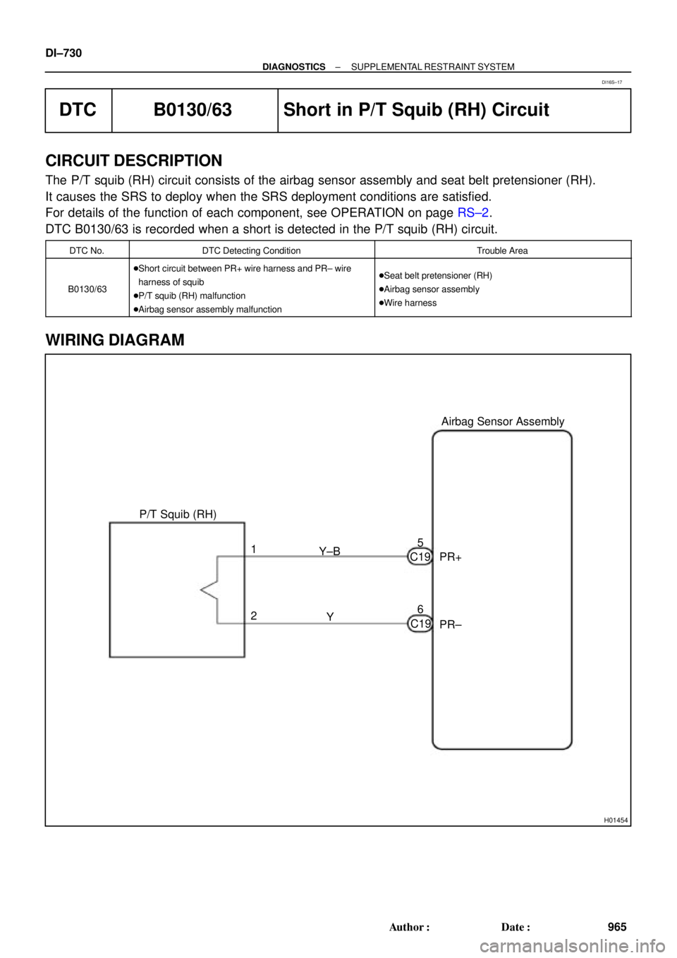
H01454
P/T Squib (RH)Airbag Sensor Assembly
PR+
PR± Y±B
Y 1
26 5
C19
C19 DI±730
± DIAGNOSTICSSUPPLEMENTAL RESTRAINT SYSTEM
965 Author�: Date�:
DTC B0130/63 Short in P/T Squib (RH) Circuit
CIRCUIT DESCRIPTION
The P/T squib (RH) circuit consists of the airbag sensor assembly and seat belt pretensioner (RH).
It causes the SRS to deploy when the SRS deployment conditions are satisfied.
For details of the function of each component, see OPERATION on page RS±2.
DTC B0130/63 is recorded when a short is detected in the P/T squib (RH) circuit.
DTC No.DTC Detecting ConditionTrouble Area
B0130/63
�Short circuit between PR+ wire harness and PR± wire
harness of squib
�P/T squib (RH) malfunction
�Airbag sensor assembly malfunction�Seat belt pretensioner (RH)
�Airbag sensor assembly
�Wire harness
WIRING DIAGRAM
DI16S±17
Page 3154 of 4770
Airbag
Sensor
Assembly
PR±
(+) (±) PR+
DI±734
± DIAGNOSTICSSUPPLEMENTAL RESTRAINT SYSTEM
969 Author�: Date�:
DTC B0131/64 Open in P/T Squib (RH) Circuit
CIRCUIT DE")
H01019H02141H02205
P/T Squib (RH)Airbag
Sensor
Assembly
PR±
(+) (±) PR+
DI±734
± DIAGNOSTICSSUPPLEMENTAL RESTRAINT SYSTEM
969 Author�: Date�:
DTC B0131/64 Open in P/T Squib (RH) Circuit
CIRCUIT DESCRIPTION
The P/T squib circuit (RH) consists of the airbag sensor assembly and seat belt pretensioner (RH).
It causes the SRS to deploy when the SRS deployment conditions are satisfied.
For details of the function of each component, see OPERATION on page RS±2.
DTC B0131/64 is recorded when an open is detected in the P/T squib (RH) circuit.
DTC No.DTC Detecting ConditionTrouble Area
B0131/64
�Open circuit in PR+ wire harness or PR± wire harness of
squib
�P/T squib (RH) malfunction
�Airbag sensor assembly malfunction�Seat belt pretensioner (RH)
�Airbag sensor assembly
�Wire harness
WIRING DIAGRAM
See page DI±730.
INSPECTION PROCEDURE
1 Prepare for inspection. (See step 1 on page DI±787)
2 Check P/T squib (RH) circuit.
CHECK:
For the connector (on the seat belt pretensioner side) between
the seat belt pretensioner (RH) and the airbag sensor assem-
bly, measure the resistance between PR+ and PR±.
OK:
Resistance: Below 1 W
NG Repair or replace harness or connector be-
tween seat belt pretensioner (RH) and airbag
sensor assembly.
OK
DI1BG±13
Page 3157 of 4770
Airbag
Sensor
Assembly
(+)
(±)PR+
± DIAGNOSTICSSUPPLEMENTAL RESTRAINT SYSTEM
DI±737
972 Author�: Date�:
DTC B0132/61 Short in P/T Squib (RH) Circuit
(to Ground)
CI")
H01019H08392H08393
P/T Squib (RH)Airbag
Sensor
Assembly
(+)
(±)PR+
± DIAGNOSTICSSUPPLEMENTAL RESTRAINT SYSTEM
DI±737
972 Author�: Date�:
DTC B0132/61 Short in P/T Squib (RH) Circuit
(to Ground)
CIRCUIT DESCRIPTION
The P/T squib (RH) circuit consists of the airbag sensor assembly and seat belt pretensioner (RH).
It causes the SRS to deploy when the SRS deployment conditions are satisfied.
For details of the function of each component, see OPERATION on page RS±2.
DTC B0132/61 is recorded when a ground short is detected in the P/T squib (RH) circuit.
DTC No.DTC Detecting ConditionTrouble Area
B0132/61
�Short circuit in P/T squib (RH) wire harness (to ground)
�P/T squib (RH) malfunction
�Airbag sensor assembly malfunction�Seat belt pretensioner (RH)
�Airbag sensor assembly
�Wire harness
WIRING DIAGRAM
See page DI±730.
INSPECTION PROCEDURE
1 Prepare for inspection. (See step 1 on page DI±787)
2 Check P/T squib (RH) circuit.
CHECK:
For the connector (on the seat belt pretensioner side) between
the seat belt pretensioner (RH) and the airbag sensor assem-
bly, measure the resistance between PR+ and body ground.
OK:
Resistance: 1 MW or Higher
NG Repair or replace harness or connector be-
tween seat belt pretensioner (RH) and airbag
sensor assembly.
OK
DI1BH±10
Page 3160 of 4770
Airbag
Sensor
Assembly
PR+
(+)
(±) ON
DI±740
± DIAGNOSTICSSUPPLEMENTAL RESTRAINT SYSTEM
975 Author�: Date�:
DTC B0133/62 Short in P/T Squib (RH) Circuit (to B")
H01019AB0119H08394H08268
P/T Squib (RH)Airbag
Sensor
Assembly
PR+
(+)
(±) ON
DI±740
± DIAGNOSTICSSUPPLEMENTAL RESTRAINT SYSTEM
975 Author�: Date�:
DTC B0133/62 Short in P/T Squib (RH) Circuit (to B+)
CIRCUIT DESCRIPTION
The P/T squib (RH) circuit consists of the airbag sensor assembly and seat belt pretensioner (RH).
It causes the SRS to deploy when the SRS deployment conditions are satisfied.
For details of the function of each component, see OPERATION on page RS±2.
DTC B0133/62 is recorded when a B+ short is detected in the P/T squib (RH) circuit.
DTC No.DTC Detecting ConditionTrouble Area
B0133/62
�Short circuit in seat belt pretensioner (RH) wire harness
(to B+)
�P/T squib (RH) malfunction
�Airbag sensor assembly malfunction�Seat belt pretensioner (RH)
�Airbag sensor assembly
�Wire harness
WIRING DIAGRAM
See page DI±730.
INSPECTION PROCEDURE
1 Prepare for inspection. (See step 1 on page DI±787)
2 Check P/T squib (RH) circuit.
CHECK:
(a) Turn ignition switch to ON.
(b) For the connector (on the seat belt pretensioner side) be-
tween the seat belt pretensioner (RH) and the airbag sen-
sor assembly, measure the voltage between PR+ and
body ground.
OK:
Voltage: 0 V
NG Repair or replace harness or connector be-
tween seat belt pretensioner (RH) and airbag
sensor assembly.
OK
DI1BI±13
Page 3163 of 4770
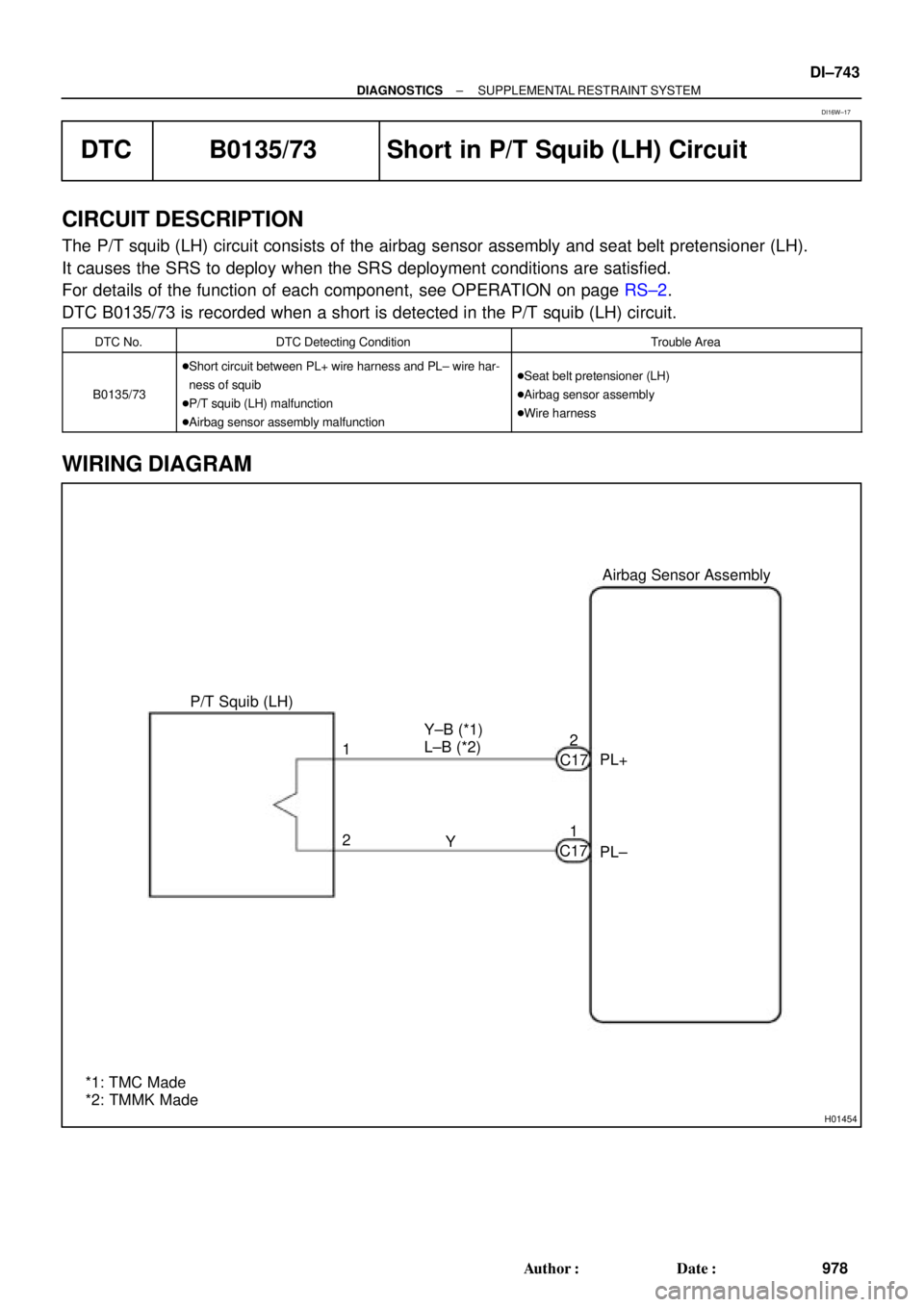
H01454
P/T Squib (LH)Airbag Sensor Assembly
PL+
PL± Y±B (*1)
L±B (*2)
Y 1
21 2
C17
C17
*1: TMC Made
*2: TMMK Made
± DIAGNOSTICSSUPPLEMENTAL RESTRAINT SYSTEM
DI±743
978 Author�: Date�:
DTC B0135/73 Short in P/T Squib (LH) Circuit
CIRCUIT DESCRIPTION
The P/T squib (LH) circuit consists of the airbag sensor assembly and seat belt pretensioner (LH).
It causes the SRS to deploy when the SRS deployment conditions are satisfied.
For details of the function of each component, see OPERATION on page RS±2.
DTC B0135/73 is recorded when a short is detected in the P/T squib (LH) circuit.
DTC No.DTC Detecting ConditionTrouble Area
B0135/73
�Short circuit between PL+ wire harness and PL± wire har-
ness of squib
�P/T squib (LH) malfunction
�Airbag sensor assembly malfunction�Seat belt pretensioner (LH)
�Airbag sensor assembly
�Wire harness
WIRING DIAGRAM
DI16W±17