Page 3037 of 4770

F00114
TRAC OFF
Indicator LightABS & TRAC ECU
CJ32 C10 R±L7
DLC2
17 J/CJ/C
2
IG3
TRC
Instrument Panel J/B
1D
J4 D319
L
A16
D R±L
C10LL
L
A16 TRAC Cut Switch
W±B12
11
LGWT
CSW
J7
J114 1
IGJ8
A 8
1JW±B
A J/C
1J7 Instrument Panel J/B
W±B
A J/CTRAC OFF
Indicator LightABS & TRAC ECU
C
C10 R±L7
DLC2
17 J/CJ/C
2
IG3
TRC
Instrument Panel J/B
1D
J4 D319
L
A16
D R±L
C10LL
L
A16 TRAC Cut Switch
W±B12
11
LGWT
CSW
J7
J114 1
IGJ8
A 8
1JW±B
A J/C
1J7 Instrument Panel J/B
W±B
A J/CTRAC OFF
Indicator LightABS & TRAC ECU
C
C10 R±L7
DLC2
17 J/CJ/C
2
IG3
TRC
Instrument Panel J/B
1D
J4 D319
L
A16
D R±L
C10LL
L
A16 TRAC Cut Switch
W±B12
11
LGWT
CSW
J7
J114 1
IGJ8
A 8
1JW±B
A J/C
1J7 Instrument Panel J/B
W±B
A J/CTRAC OFF
Indicator LightABS & TRAC ECU
C10 R±L7
DLC2
17 J/CJ/C
2
IG3
TRC
Instrument Panel J/B
1D
J4 D319
L
A16
D R±L
C10LL
L
A16 TRAC Cut Switch
W±B12
11
LGWT
CSW
J7
J114 1
IGJ8
A 8
1JW±B
A J/C
1J7 Instrument Panel J/B
W±B
A J/C
TRAC OFF
Indicator LightABS & TRAC ECU
C10
GAUGER±L7
DLC2
17 J/CJ/C
2
IG3
TRC
Instrument Panel J/B
1D
J4 D319
L
A16
D R±L
C10LL
L
A16 TRAC Cut Switch
W±B12
11
LGWT
CSW
J7
J114 1
IGJ8
A 8
1JW±B
A J/C
1J7 Instrument Panel J/B
W±B
A J/CJ32 J32
± DIAGNOSTICSABS & TRACTION CONTROL SYSTEM
DI±617
852 Author�: Date�:
TRAC OFF Indicator, TRAC Cut Switch Circuit
CIRCUIT DESCRIPTION
This is the TRAC control main switch. When the TRAC cut switch is pushed on, TRAC control goes off and
the TRAC OFF indicator lights up. This indicator blinks for warnings when the trouble occurs and for
displaying DTC.
WIRING DIAGRAM
INSPECTION PROCEDURE
1 Check DTC.
Check DTC on page DI±574.
YES Repair circuit indicated by the code output.
NO
DI04Y±04
Page 3040 of 4770

F00097
Instrument Panel J/B
1DR±L
C10 C8 IND 2J/C
J4LG18
A16 R±LSLIP Indicator LightABS & TRAC ECU
IG3 75
LG3
D D Instrument Panel J/B
1DR±L
C10 C8 IND 2J/C
J4LG18
A16 R±LSLIP Indicator LightABS & TRAC ECU
IG3 75
LG3
D D Instrument Panel J/B
1DR±L
C10 C8 IND 2J/C
J4LG18
A16 R±LSLIP Indicator LightABS & TRAC ECU
IG3 75
LG3
D D Instrument Panel J/B
1DR±L
C10 C8 IND 2J/C
J4LG18
A16 R±LSLIP Indicator LightABS & TRAC ECU
IG3 75
LG3
D D Instrument Panel J/B
1DR±L
C10 C8 IND 2J/C
J4LG18
A16 R±LSLIP Indicator LightABS & TRAC ECU
IG3 75
LG3
D D Instrument Panel J/B
1DR±L
C10 C8 IND 2J/C
J4LG18
A16 R±LSLIP Indicator LightABS & TRAC ECU
IG3 75
LG3
D DInstrument Panel J/B
1DR±L
C10 C8 IND 2
GAUGEJ/C
J4LG18
A16 R±LSLIP Indicator LightABS & TRAC ECU
IG3 75
LG3
D D
DI±620
± DIAGNOSTICSABS & TRACTION CONTROL SYSTEM
855 Author�: Date�:
SLIP Indicator Light Circuit
CIRCUIT DESCRIPTION
The SLIP indicator blinks during TRAC operation.
WIRING DIAGRAM
INSPECTION PROCEDURE
1 Check SLIP indicator light.
See combination meter troubleshooting on page BE±2.
NG Repair or replace combination meter.
OK
2 Check for short circuit in harness and connector between ABS & TRAC ECU and
SLIP indicator light (See page IN±31).
NG Repair or replace harness or connector.
OK
Check and replace ABS & TRAC ECU.
DI04Z±04
Page 3041 of 4770
F00120
DLC2
ECII3
ADLC1 6
12
Tc
BJ3
J22J/C
II3A15 IK2 J8
11 J7 E
1
C
BRA
ABR BRBRJ/C
BR
TcTc
E
1LG±RJ/C
BB B LG±R LG±RLG±RABS & TRAC ECU
9
34
113
DLC2
ECII3
ADLC1 6
12
Tc
BJ3
J22J/CLG±R
*1
II3A15 IK2 J8
11 J7 E
1
C
BRA
ABR BRBRJ/C
BR
TcTc
E
1LG±RJ/C
BB B LG±R LG±RLG±RABS & TRAC ECU
9
34
113
P±B*2
*1:
TMC Made*2: TMMK Made
F02607 F00445F02612
DLC2
DLC1
Tc E
1
Tc E
1
± DIAGNOSTICSABS & TRACTION CONTROL SYSTEM
DI±621
856 Author�: Date�:
Tc Terminal Circuit
CIRCUIT DESCRIPTION
Connecting between terminals Tc and E1 of the DLC1 or the DLC2 causes the ECU to display the DTC by
blinking the ABS warning light and TRAC OFF indicator light.
WIRING DIAGRAM
INSPECTION PROCEDURE
1 Check voltage between terminals Tc and E1 of DLC2 or DLC1.
CHECK:
(a) Turn the ignition switch ON.
(b) Measure voltage between terminals Tc and E
1 of DLC2 or
DLC1.
OK:
Voltage: 10 ± 14 V
OK If ABS warning light does not blink even after Tc
and E
1 are connected, the ECU may be defec-
tive.
NG
DI4KY±01
Page 3060 of 4770
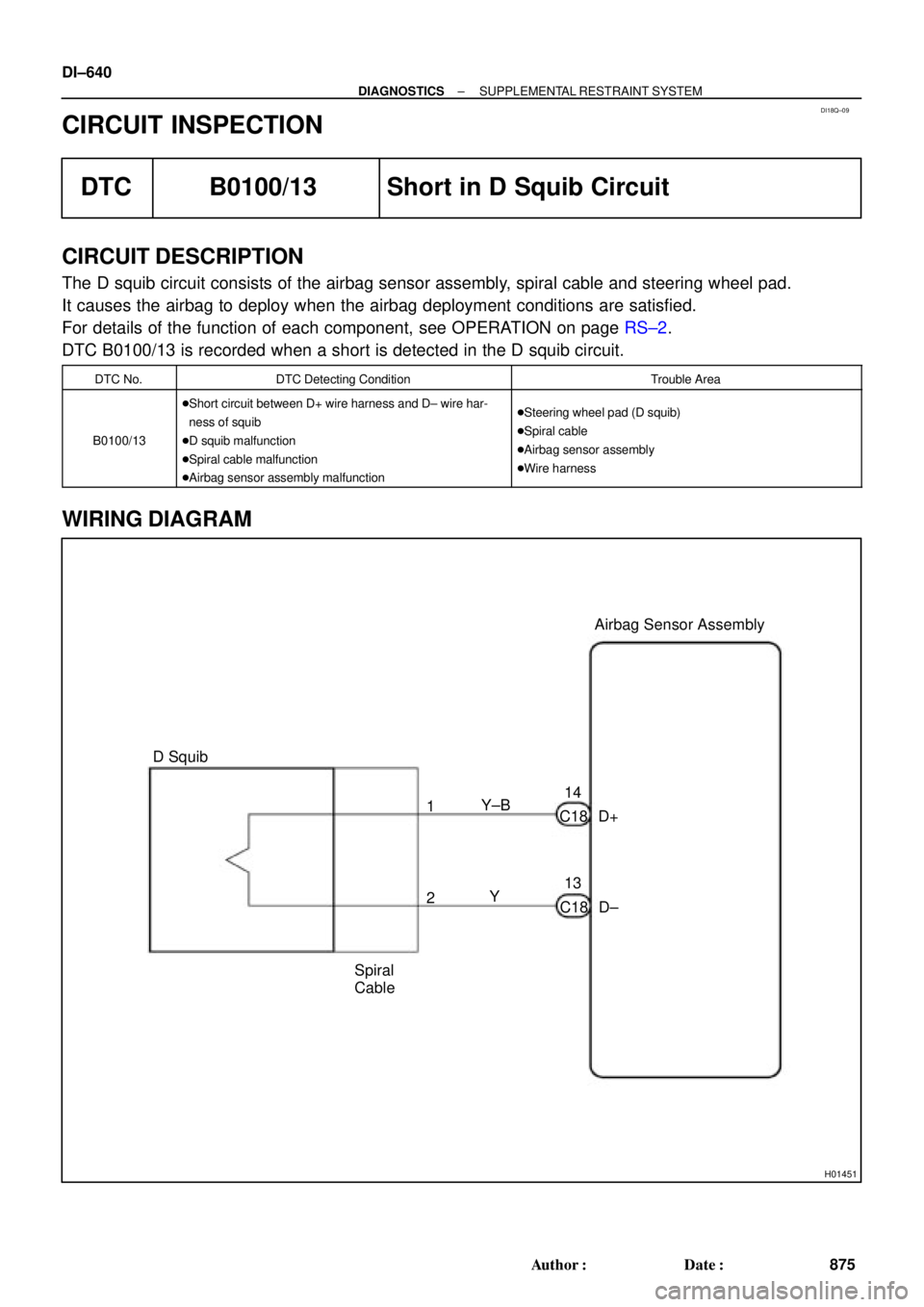
DI18Q±09
H01451
Y±B
D+ C1814Airbag Sensor Assembly
13
C18 D± Y 1
2
Spiral
Cable D Squib DI±640
± DIAGNOSTICSSUPPLEMENTAL RESTRAINT SYSTEM
875 Author�: Date�:
CIRCUIT INSPECTION
DTC B0100/13 Short in D Squib Circuit
CIRCUIT DESCRIPTION
The D squib circuit consists of the airbag sensor assembly, spiral cable and steering wheel pad.
It causes the airbag to deploy when the airbag deployment conditions are satisfied.
For details of the function of each component, see OPERATION on page RS±2.
DTC B0100/13 is recorded when a short is detected in the D squib circuit.
DTC No.DTC Detecting ConditionTrouble Area
B0100/13
�Short circuit between D+ wire harness and D± wire har-
ness of squib
�D squib malfunction
�Spiral cable malfunction
�Airbag sensor assembly malfunction�Steering wheel pad (D squib)
�Spiral cable
�Airbag sensor assembly
�Wire harness
WIRING DIAGRAM
Page 3065 of 4770
 (+)D±
± DIAGNOSTICSSUPPLEMENTAL RESTRAINT SYSTEM
DI±645
880 Author�: Date�:
DTC B0101/14 Open in D Squib Circuit
CIRCUIT DES")
R14286H01001H01139
D SquibSpiral
Cable
Airbag
Sensor
Assembly
D+ u"
(±) (+)D±
± DIAGNOSTICSSUPPLEMENTAL RESTRAINT SYSTEM
DI±645
880 Author�: Date�:
DTC B0101/14 Open in D Squib Circuit
CIRCUIT DESCRIPTION
The D squib circuit consists of the airbag sensor assembly, spiral cable and steering wheel pad.
It causes the airbag to deploy when the airbag deployment conditions are satisfied.
For details of the function of each component, see OPERATION on page RS±2.
DTC B0101/14 is recorded when an open is detected in the D squib circuit.
DTC No.DTC Detecting ConditionTrouble Area
B0101/14
�Open circuit in D+ wire harness or D± wire harness of
squib
�D squib malfunction
�Spiral cable malfunction
�Airbag sensor assembly malfunction�Steering wheel pad (D squib)
�Spiral cable
�Airbag sensor assembly
�Wire harness
WIRING DIAGRAM
See page DI±640.
INSPECTION PROCEDURE
1 Prepare for inspection. (See step 1 on page DI±787)
2 Check D squib circuit.
CHECK:
For the connector (on the spiral cable side) between the spiral
cable and the steering wheel pad, measure the resistance be-
tween D+ and D±.
OK:
Resistance: Below 1 W
NG Go to step 5.
OK
DI18R±16
Page 3069 of 4770

CIRCUIT DESCR")
H01001R14301H01126
D SquibSpiral
Cable
Airbag
Sensor
Assembly
D+
± DIAGNOSTICSSUPPLEMENTAL RESTRAINT SYSTEM
DI±649
884 Author�: Date�:
DTC B0102/11 Short in D Squib Circuit (to Ground)
CIRCUIT DESCRIPTION
The D squib circuit consists of the airbag sensor assembly, spiral cable and steering wheel pad.
It causes the SRS to deploy when the SRS deployment conditions are satisfied.
For details of the function of each component, see OPERATION on page RS±2.
DTC B0102/11 is recorded when a ground short is detected in the D squib circuit.
DTC No.DTC Detecting ConditionTrouble Area
B0102/11
�Short circuit in D squib wire harness (to ground)
�D squib malfunction
�Spiral cable malfunction
�Airbag sensor assembly malfunction�Steering wheel pad (D squib)
�Spiral cable
�Airbag sensor assembly
�Wire harness
WIRING DIAGRAM
See page DI±640.
INSPECTION PROCEDURE
1 Prepare for inspection. (See step 1 on page DI±787)
2 Check D squib circuit.
CHECK:
For the connector (on the spiral cable side) between the spiral
cable and the steering wheel pad, measure the resistance be-
tween D+ and body ground.
OK:
Resistance: 1 MW or Higher
NG Go to step 5.
OK
DI4L2±01
Page 3073 of 4770
 (+)
ON
± DIAGNOSTICSSUPPLEMENTAL RESTRAINT SYSTEM
DI±653
888 Author�: Date�:
DTC B0103/12 Short in D Squib Circuit (to B")
H01001
R14288AB0119
H04530
D SquibSpiral
Cable
Airbag
Sensor
Assembly
D+
(±) (+)
ON
± DIAGNOSTICSSUPPLEMENTAL RESTRAINT SYSTEM
DI±653
888 Author�: Date�:
DTC B0103/12 Short in D Squib Circuit (to B+)
CIRCUIT DESCRIPTION
The D squib circuit consists of the airbag sensor assembly, spiral cable and steering wheel pad.
It causes the SRS to deploy when the SRS deployment conditions are satisfied.
For details of the function of each component, see OPERATION on page RS±2.
DTC B0103/12 is recorded when a B+ short is detected in the D squib circuit.
DTC No.DTC Detecting ConditionTrouble Area
B0103/12
�Short circuit in D squib wire harness (to B+)
�D squib malfunction
�Spiral cable malfunction
�Airbag sensor assembly malfunction�Steering wheel pad (D squib)
�Spiral cable
�Airbag sensor assembly
�Wire harness
WIRING DIAGRAM
See page DI±640.
INSPECTION PROCEDURE
1 Prepare for inspection. (See step 1 on page DI±787)
2 Check D squib circuit.
CHECK:
(a) Turn ignition switch to ON.
(b) For the connector (on the spiral cable side) between the
spiral cable and the steering wheel pad, measure the volt-
age between D+ and body ground.
OK:
Voltage: 0 V
NG Go to step 5.
OK
DI4L3±01
Page 3077 of 4770
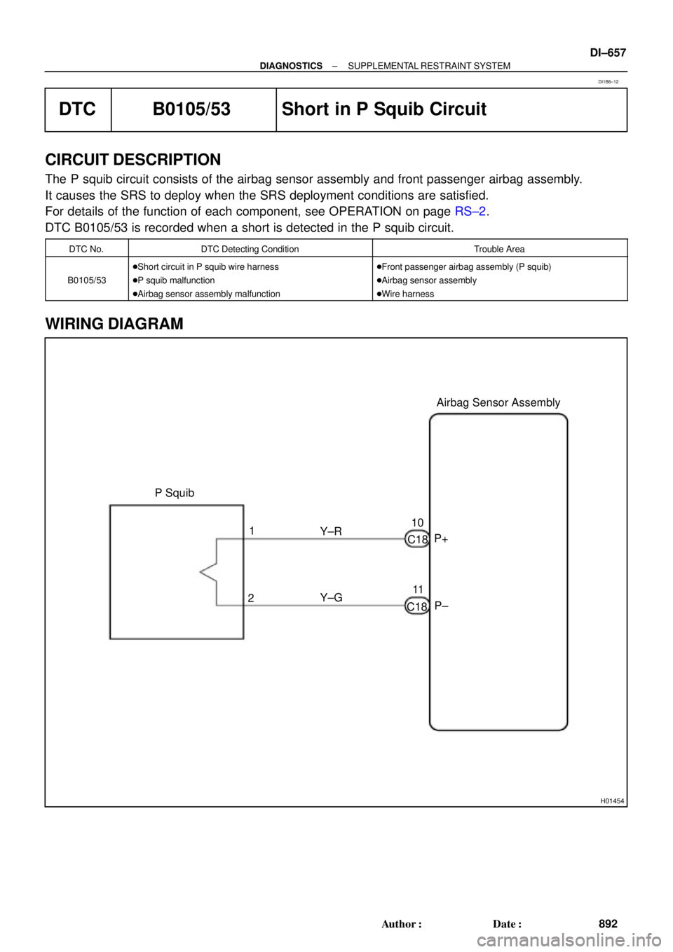
H01454
P Squib
10Airbag Sensor Assembly
2Y±R
C18
Y±G 1
11
C18P+
P±
± DIAGNOSTICSSUPPLEMENTAL RESTRAINT SYSTEM
DI±657
892 Author�: Date�:
DTC B0105/53 Short in P Squib Circuit
CIRCUIT DESCRIPTION
The P squib circuit consists of the airbag sensor assembly and front passenger airbag assembly.
It causes the SRS to deploy when the SRS deployment conditions are satisfied.
For details of the function of each component, see OPERATION on page RS±2.
DTC B0105/53 is recorded when a short is detected in the P squib circuit.
DTC No.DTC Detecting ConditionTrouble Area
B0105/53
�Short circuit in P squib wire harness
�P squib malfunction
�Airbag sensor assembly malfunction�Front passenger airbag assembly (P squib)
�Airbag sensor assembly
�Wire harness
WIRING DIAGRAM
DI1B6±12