Page 2981 of 4770
F00125
MAIN
Battery ALT F4B±R
F91B
1C
STOP
B±G4
1 Instrument Panel J/B
FL Block
1 7 WA6
21S 5IK3 J28
G±WECU
J27
1RSTP
Stop Light SwitchJ/C
7
G±R
H10Light Failure
Sensor R
W±B A
R9 R11 C14
BP BL 11R
2
4
G±W G±W G±WG±W 1
Instrument
Panel J/B
2 1
G±RG±R
W±B W±B
W±B H10R9
R11
J/C
A A High
Mounted
Stop
LightRight
Stop
LightLeft
Stop
Light
J405 2
12
2
5
W±B
W±B
± DIAGNOSTICSANTI±LOCK BRAKE SYSTEM (BOSCH Made)
DI±561
796 Author�: Date�:
DTC 58 Stop Light Switch Circuit
CIRCUIT DESCRIPTION
DTC No.DTC Detecting ConditionTrouble Area
49
Stop light switch circuit is open, and stop light switch
voltage is in the level between 65 % or more and less
than 93 % of the battery voltage.�Stop light switch
�Stop light switch circuit
�ECU
WIRING DIAGRAM
INSPECTION PROCEDURE
1 Check operation of stop light.
CHECK:
Check that stop light lights up when brake pedal is depressed and turns off when brake pedal is released.
NG Repair stop light circuit (See page BE±36).
OK
DI046±09
Page 2985 of 4770
F00096
J/C
J4 D
ABS 7
C
R±LC10
1D
GAUGE
A6 4
DLC2ECU
Instrument
Panel J/BABS
Warning
Light
210
IG312
C10
DR±L R±L
WA 21
14 R±LJ/C
J29
C
C R±L
R±LR±L
IK3
± DIAGNOSTICSANTI±LOCK BRAKE SYSTEM (BOSCH Made)
DI±565
800 Author�: Date�:
ABS Warning Light Circuit
CIRCUIT DESCRIPTION
If the ECU detects any trouble, it lights the ABS warning light while at the same time prohibiting ABS control.
At this time, the ECU records a DTC in memory.
Connect terminals Tc and E
1 of the DLC1 or DLC2 to make the ABS warning light blink and output the DTC.
WIRING DIAGRAM
INSPECTION PROCEDURE
Troubleshoot in accordance with the chart below for each trouble symptom
ABS warning light does not light upGo to step 1
ABS warning light remains onGo to step 2
1 Check ABS warning light.
See combination meter troubleshooting on page BE±2.
NG Repair bulb or combination meter assembly.
OK
Check for open circuit in harness and connector between GAUGE fuse, DLC2 and ABS ECU
(See page IN±31).
DI048±08
Page 2987 of 4770
F00120
LG±RECU
A6 IK212 J/C
J3
E1
J23: (5S±FE)4
J22: (1MZ±FE)B Tc
A12
3LG±R LG±R
LG±RB B
Tc
E
1J/C
A ADLC2
BR
DLC1
11II3
ECBR
BR
BR311
BRTc II3J/C
J8
J7C
B 6
LG±RECU
A6 IK212 J/C
J3
E1
J23: (5S±FE)4
J22: (1MZ±FE)B Tc
A12
3LG±R LG±R
LG±RB B
Tc
E
1J/C
A ADLC2
BR
DLC1
11II3
ECBR
BR
BR311
BRTc II3J/C
J8
J7C
B 6
P±B (1MZ±FE)
LG±R (5S±FE)
F02607 F00445F02612
DLC2
DLC1
Tc E
1
Tc E
1
± DIAGNOSTICSANTI±LOCK BRAKE SYSTEM (BOSCH Made)
DI±567
802 Author�: Date�:
Tc Terminal Circuit
CIRCUIT DESCRIPTION
Connecting between terminals Tc and E1 of the DLC1 or the DLC2 causes the ECU to display the DTC by
flashing the ABS warning light.
WIRING DIAGRAM
INSPECTION PROCEDURE
1 Check voltage between terminals Tc and E1 of DLC2 or DLC1.
CHECK:
(a) Turn the ignition switch ON.
(b) Measure voltage between terminals Tc and E
1 of DLC2 or
DLC1.
OK:
Voltage: 10 ± 14 V
OK If ABS warning light does not blink even after Tc
and E
1 are connected, the ECU may be defec-
tive.
NG
DI049±08
Page 2989 of 4770
F00095
11ECU
R±Y
AA6 IK2
3
J/CDLC1
BR
Ts
J22: (1MZ±FE)16
EC5
E
1Ts
BRAII38
J23: (5S±FE)R±Y
11ECU
R±Y
AA6 IK2
3
J/CDLC1
BR
Ts
J22: (1MZ±FE)165
E
1Ts
BRAII38
J23: (5S±FE)R±Y B±Y (1MZ±FE)
LG (5S±FE)
AB0119S08096
F00446DLC1 DLC1
DLC1
DLC1
DLC1
Ts
DLC1 E1
ON
± DIAGNOSTICSANTI±LOCK BRAKE SYSTEM (BOSCH Made)
DI±569
804 Author�: Date�:
Ts Terminal Circuit
CIRCUIT DESCRIPTION
The sensor check circuit detects abnormalities in the speed sensor signal which cannot be detected with
the DTC check.
Connecting terminals Ts and E
1 of the DLC1 in the engine compartment starts the check.
WIRING DIAGRAM
INSPECTION PROCEDURE
1 Check voltage between terminals Ts and E1 of DLC1.
CHECK:
(a) Turn the ignition switch ON.
(b) Measure voltage between terminals Ts and E
1 of DLC1.
OK:
Voltage: 10 ± 14 V
OK If ABS warning light does not blink even after Ts
and E
1 are connected, the ECU may be defec-
tive.
NG
DI04A±08
Page 3004 of 4770

DI04J±04
F03951
ABS & TRAC Solenoid Relay
Battery
MAINB±G1F4 ALT1F5 B±G
FL
BlockW±B
EA 3 ABS
12
3 Engine Room R/B No. 3
1
2
336
4
53
3
3
W±L
A8
4ABS & TRAC
Actuator
ABS & TRAC
ECU
5
A8R
A1510
AST GR
GR±RABS & TRAC
ECU
11
A15
1
A15SR
R+
DLC1 DI±584
± DIAGNOSTICSABS & TRACTION CONTROL SYSTEM
819 Author�: Date�:
CIRCUIT INSPECTION
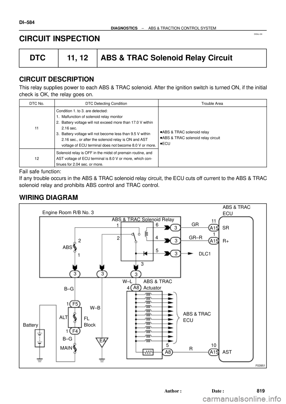
DTC 11, 12 ABS & TRAC Solenoid Relay Circuit
CIRCUIT DESCRIPTION
This relay supplies power to each ABS & TRAC solenoid. After the ignition switch is turned ON, if the initial
check is OK, the relay goes on.
DTC No.DTC Detecting ConditionTrouble Area
11
Condition 1. to 3. are detected:
1. Malfunction of solenoid relay monitor
2. Battery voltage will not exceed more than 17.0 V within
2.16 sec.
3. Battery voltage will not become less than 9.5 V within
2.16 sec., or after the solenoid relay is ON and AST
voltage of ECU terminal does not become 8.0 V or more.
�ABS & TRAC solenoid relay
�ABS & TRAC solenoid relay circuit
�ECU
12
Solenoid relay is OFF in the midst of premain routine, and
AST voltage of ECU terminal is 8.0 V or more, which con-
tinues for 2.04 sec. or more.
Fail safe function:
If any trouble occurs in the ABS & TRAC solenoid relay circuit, the ECU cuts off current to the ABS & TRAC
solenoid relay and prohibits ABS control and TRAC control.
WIRING DIAGRAM
Page 3007 of 4770

F03413
Battery2
Engine Room R/B No. 3
MAIN B±G F4F5
FL
BlockABS
12
3
1ALT1
31 B±GABS & TRAC
Motor Relay
4
33
3GR±L
GR±R24
A15
1
A15ABS & TRAC ECU
MR
R+
MT
A1514
R±W
A83 ABS & TRAC Actuator
W±R2
A8
1
A8
W±B
EA
± DIAGNOSTICSABS & TRACTION CONTROL SYSTEM
DI±587
822 Author�: Date�:
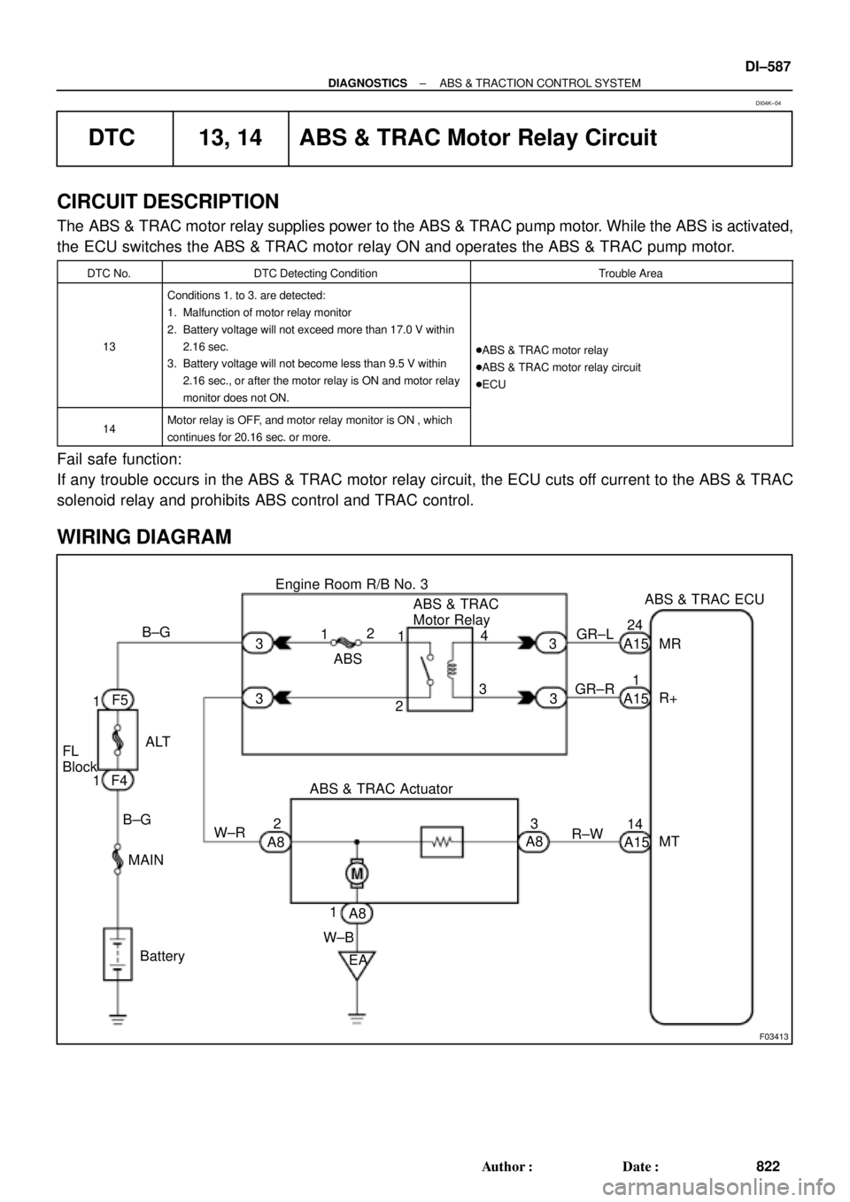
DTC 13, 14 ABS & TRAC Motor Relay Circuit
CIRCUIT DESCRIPTION
The ABS & TRAC motor relay supplies power to the ABS & TRAC pump motor. While the ABS is activated,
the ECU switches the ABS & TRAC motor relay ON and operates the ABS & TRAC pump motor.
DTC No.DTC Detecting ConditionTrouble Area
13
Conditions 1. to 3. are detected:
1. Malfunction of motor relay monitor
2. Battery voltage will not exceed more than 17.0 V within
2.16 sec.
3. Battery voltage will not become less than 9.5 V within
2.16 sec., or after the motor relay is ON and motor relay
monitor does not ON.
�ABS & TRAC motor relay
�ABS & TRAC motor relay circuit
�ECU
14Motor relay is OFF, and motor relay monitor is ON , which
continues for 20.16 sec. or more.
Fail safe function:
If any trouble occurs in the ABS & TRAC motor relay circuit, the ECU cuts off current to the ABS & TRAC
solenoid relay and prohibits ABS control and TRAC control.
WIRING DIAGRAM
DI04K±04
Page 3011 of 4770

F03952
SRLH
10
SR
R+
SFLR
SRRR
SRC2
AST
10
SFLR
SRRR
SRC2
AST Battery
MAIN
B±G1F4
ALT
1 B±G
F5
FL
Block
W±B
EA 3
333 2 ABS
12 Engine Room R/B No. 3
ABS & TRAC
Solenoid
Relay
16 33
3
4
5
W±L DLC1GR
GR±R
4A8ABS & TRAC ECU
ABS & TRAC ActuatorA7
A7
A7
A7
A7
A7
A7
A7
A7
A7
A7
A7
A89
10
12
11
3
4
6
5
7
2
8
1
5R±B
G±Y
L±B
W±R
W±R
LG±B
W±L
R±G
B±R
B±Y
Y±R
Y±B
R11
A15
1A15
13
A15
25
A15
2A17
8A17
26
A15
12
A15
1A17
7A17
5A17
4A17
12
A17
6A17
A15
SFLH
SRRH
SFRR
SRLR
SRC1
SMC1
SMC2 SFRH
F00057
1 2 3
4 5 6
7
8 9 10 11 12
A7
4
1 2 3
4 5 6
7
8 9 10 11 12
A7
4
1 2 3
4 5 6
7
8 9 10 11 12
A7
4
1 2 3
4 5 6
7
8 9 10 11 12
A7
4
1 2 3
4 5 6
7
8 9 10 11 12
A7
41 2 3
4 5 6
7
8 9 10 11 12A8
A74
± DIAGNOSTICSABS & TRACTION CONTROL SYSTEM
DI±591
826 Author�: Date�:
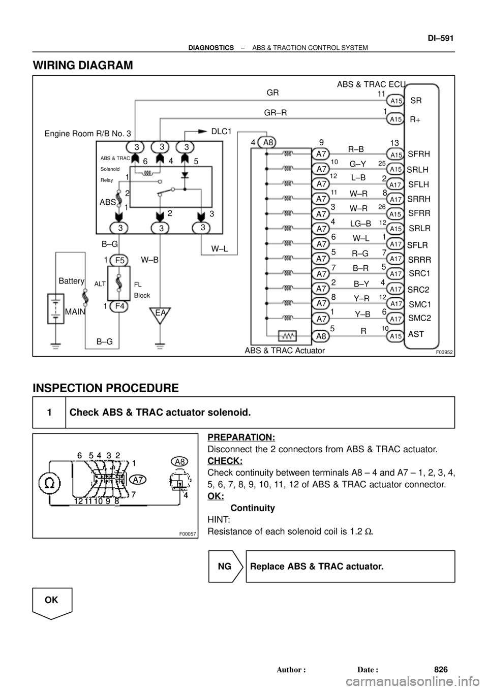
WIRING DIAGRAM
INSPECTION PROCEDURE
1 Check ABS & TRAC actuator solenoid.
PREPARATION:
Disconnect the 2 connectors from ABS & TRAC actuator.
CHECK:
Check continuity between terminals A8 ± 4 and A7 ± 1, 2, 3, 4,
5, 6, 7, 8, 9, 10, 11, 12 of ABS & TRAC actuator connector.
OK:
Continuity
HINT:
Resistance of each solenoid coil is 1.2 W.
NG Replace ABS & TRAC actuator.
OK
Page 3014 of 4770
F00116
ABS & TRAC ECU
A15
A16 B
G6W
12
R
IK2
IL1 Left Front
Speed SensorRight Front
Speed Sensor
B
G R
Left Rear
Speed Sensor Right Rear
Speed Sensor2
1
1
2
2
1A15
A15
A15
A16
A16
A16 R
IK21
G
W
IL11 2FR+
FL+
FL±
RR+ 17
RL+
RL± 4 18
5FR±
RR± 10
ID19
ID12
1 93ABS & TRAC ECU
A15
A16 B
G6W
12
R
IK2
IL1 Right Front
Speed Sensor
B
W
*1
G R
Left Rear
Speed Sensor2
1
1
2
2
1A15
A15
A15
A16
A16
A16 R
IK21
G
W
IL11 2FR+
FL+
FL±
RR+ 17
RL+
RL± 4 18
5FR±
RR± 10
ID19
ID12
1 93
Y
*2
G*1
BR*2
B*1
Y*2
W*1
P*2
*1
: TMC Made*2: TMMK Made DI±594
± DIAGNOSTICSABS & TRACTION CONTROL SYSTEM
829 Author�: Date�:
WIRING DIAGRAM