Page 2952 of 4770
F00113
A19
EC
BRTc LG±R
AA A BRII36
BR
311 DLC1Tc
E
1
Tc E1
LG±RLG±R
II3 11 BRC
BJ/C
J22: (1MZ±FE)
J23: (5S±FE)BRDLC2
34LG±R
BB
B J3ABS ECU
J8 J7
J/CJ/C
A19
EC
BRTc 8
LG±R
AA A BRII36
BR
311 DLC1Tc
E
1
Tc E1
LG±RLG±R
II3 11 BRC
BJ/C
J22: (1MZ±FE)
J23: (5S±FE)BRDLC2
34LG±R
BB
B J3ABS ECU
J8 J7
J/CJ/C
F02607 F00445F02612
DLC2
DLC1
Tc E
1
Tc E
1
DI±532
± DIAGNOSTICSANTI±LOCK BRAKE SYSTEM (DENSO Made)
767 Author�: Date�:
Tc Terminal Circuit
CIRCUIT DESCRIPTION
Connecting between terminals Tc and E1 of the DLC1 or the DLC2 causes the ECU to display the DTC by
flashing the ABS warning light.
WIRING DIAGRAM
INSPECTION PROCEDURE
1 Check voltage between terminals Tc and E1 of DLC2 or DLC1.
CHECK:
(a) Turn the ignition switch ON.
(b) Measure voltage between terminals Tc and E
1 of DLC2 or
DLC1.
OK:
Voltage: 10 ± 14 V
OK If ABS warning light does not blink even after Tc
and E
1 are connected, the ECU may be defec-
tive.
NG
DI03R±03
Page 2954 of 4770
F00172
J/C
EC BRA
ABR
3
16 DLC1
Ts E
1
R±Y
II38
R±Y
A198
TsABS ECU
J22: (1MZ±FE)
J23: (5S±FE)
J/C
BRA
ABR
3
16 DLC1
Ts E
1
R±Y
II38
R±Y
A198
TsABS ECU
J22: (1MZ±FE)
J23: (5S±FE)
AB0119S08096
F00446DLC1 DLC1
DLC1
DLC1DLC1
Ts
DLC1 E1
ON
DI±534
± DIAGNOSTICSANTI±LOCK BRAKE SYSTEM (DENSO Made)
769 Author�: Date�:
Ts Terminal Circuit
CIRCUIT DESCRIPTION
The sensor check circuit detects abnormalities in the speed sensor signal which cannot be detected with
the DTC check.
Connecting terminals Ts and E
1 of the DLC1 in the engine compartment starts the check.
WIRING DIAGRAM
INSPECTION PROCEDURE
1 Check voltage between terminals Ts and E1 of DLC1.
CHECK:
(a) Turn the ignition switch ON.
(b) Measure voltage between terminals Ts and E
1 of DLC1.
OK:
Voltage: 10 ± 14 V
OK If ABS warning light does not blink even after Ts
and E
1 are connected, the ECU may be defec-
tive.
NG
DI03S±03
Page 2966 of 4770

DI040±08
F03949
Actuator Assembly
BatteryActuator Assembly
MAINB±GF4 1 ALT
FL
Block 1F5 B±G3
ABS
12 3
Engine
Room R/B
No.3L
L
18
A6
+B+BA6
Valve Relay
Motor Relay17
A6 16 GND2
W±BEA
W±B
W±B 19
A6GND1 ECU DI±546
± DIAGNOSTICSANTI±LOCK BRAKE SYSTEM (BOSCH Made)
781 Author�: Date�:
CIRCUIT INSPECTION
DTC 11 ABS Solenoid Valve Relay Circuit
CIRCUIT DESCRIPTION
This relay supplies power to each ABS solenoid. After the ignition switch is turned ON, if the initial check is
OK, the relay goes on.
DTC No.DTC Detecting ConditionTrouble Area
11
Detection of any conditions from 1. through 3.:
1. 3 or more solenoid valves are shown faulty in response
and simultaneously valve supply voltage is detected
faulty.
2. Solenoid valve relay will not be switched OFF.
3. Valve relay is frozen in spite of its high valve relay sup-
ply voltage.
�ABS solenoid valve relay
�Valve supply voltage
�ECU
Fail safe function:
If trouble occurs in the ABS solenoid valve relay circuit, the ECU cuts off current to the ABS solenoid valve
relay and prohibits ABS control.
WIRING DIAGRAM
Page 2968 of 4770

F03949
Actuator Assembly
BatteryActuator Assembly
MAINB±GF4 1 ALT
FL
Block 1F5 B±G3
ABS
12 3L
L
18
A6
+B+BA6
Valve Relay
Motor Relay17
A6 16 GND2
W±BEA
W±B
W±B 19
A6GND1 ECU Engine
Room R/B
No.3 DI±548
± DIAGNOSTICSANTI±LOCK BRAKE SYSTEM (BOSCH Made)
783 Author�: Date�:
DTC 13 Pump Motor Circuit
CIRCUIT DESCRIPTION
The ABS motor relay supplies power to the ABS pump motor. While the ABS is activated, the ECU switches
the ABS motor relay ON and operates the ABS pump motor.
DTC No.DTC Detecting ConditionTrouble Area
13
Detection of any conditions from (1) through (3):
1. After actuation of the motor relay, pump motor voltage
will not be supplied within 0.4 sec.
2. Pump motor voltage is at a high level, motor relay will
not actuate for 2.5 sec. or more.
3. Pump motor voltage keeps low level for longer than 0.4
sec. and the pump repeats activating for 7 sec. 3 times
maximally. since the last activation, the pump motor has
been gone dead because of short circuit.
�ABS motor relay
�Pump motor voltage
�Pump motor lead disconnected
�ECU
Fail safe function:
If trouble occurs in the ABS motor relay circuit, the ECU cuts off current to the ABS solenoid relay and prohib-
its ABS control.
WIRING DIAGRAM
DI041±08
Page 2970 of 4770
F03949
Actuator Assembly
BatteryActuator Assembly
MAINB±GF4 1 ALT
FL
Block 1F5 B±G3
ABS
12 3
Engine
Room R/B
No.3L
L
18
A6
+B+BA6
Valve Relay
Motor Relay17
A6 16 GND2
W±BEA
W±B
W±B 19
A6GND1 ECU DI±550
± DIAGNOSTICSANTI±LOCK BRAKE SYSTEM (BOSCH Made)
785 Author�: Date�:
DTC 21, 22, 23, 24 ABS Solenoid Valve Circuit
CIRCUIT DESCRIPTION
This solenoid goes on when signals are received from the ECU and controls the pressure acting on the wheel
cylinders thus controlling the braking force.
DTC No.DTC Detecting ConditionTrouble Area
21, 22, 23, 24Solenoid valve signal does not match to the check result.�Each solenoid valve
Fail safe function:
If trouble occurs in the actuator solenoid valve circuit, the ECU cuts off current to the ABS solenoid valve
relay and prohibits ABS control.
WIRING DIAGRAM
DI042±08
Page 2973 of 4770
F00086
Right Front
Speed Sensor
Left Front
Speed Sensor
Right Rear
Speed Sensor
Left Rear
Speed SensorECU
FR+
FR±
FL+
FL±
RR+
RR±
RL+
RL± A6
A6
A6
A6
A6
A6
A6
A65
4
7
6
3
1
9
8 W
B
R
G
P
L
Y
BRR
G
PP
L
L
Y
Y
BR
BR 2
1
2
1
1
2
1
2IK2
IL1IK3
ID1IK2
IL1 IK3
ID1IK3
IK3 22 1
6
1
3
93
9 6Right Front
Speed Sensor
Left Front
Speed Sensor
Right Rear
Speed Sensor
Left Rear
Speed SensorECU
FR+
FR±
FL+
FL±
RR+
RR±
RL+
RL± A6
A6
A6
A6
A6
A6
A6
A65
4
7
6
3
1
9
8 W
B
R
G
P
L
Y
BRR
G
PP
L
L
Y
Y
BR
BR 2
1
2
1
1
2
1
2IK2
IL1IK3
ID1IK2
IL1 IK3
ID1IK3
IK3 22 1
6
1
3
93
9 6
± DIAGNOSTICSANTI±LOCK BRAKE SYSTEM (BOSCH Made)
DI±553
788 Author�: Date�:
WIRING DIAGRAM
Page 2978 of 4770

F03950
Actuator Assembly LB±R
IG1Actuator Assembly LB±R
IG1Actuator Assembly LB±R
IG1Actuator Assembly LB±R
IG1Actuator Assembly L
IG1
BatteryMAINB±G1
F4 ALTFL
Block 1F5 B±G3
ABS
12
Engine
Room R/B
No.3 3L
18
A617
A6
+B+B
Valve Relay
Motor Relay
GND2
A6
1615
A65
B±R
IK3B±R
C
C
J12 J/C
ECU
GND119
A6W±B
W±B
W±B
EAECU±IG
Instrument
Panel J/B 1J
9 DI±558
± DIAGNOSTICSANTI±LOCK BRAKE SYSTEM (BOSCH Made)
793 Author�: Date�:
DTC 41 Power Source Circuit
CIRCUIT DESCRIPTION
This is the power source for the ECU, hence the actuators.
DTC No.DTC Detecting ConditionTrouble Area
41
Vehicle speed at about 6 km/h (4 mph), low battery voltage
is less than 9.4 V at the time of non±operation of ABS
control or less than 8.8 V at the time of operation of ABS
control, and high battery voltage is more than 17.4 V.�Battery
�Charging system
�Power source circuit
�ECU
Fail safe function:
If trouble occurs in the power source circuit, the ECU cuts off current to the ABS solenoid valve relay and
prohibits ABS control.
WIRING DIAGRAM
DI045±08
Page 2979 of 4770
F00073
ECU±IG
Instrument
Panel J/BECU±IG
Instrument
Panel J/BECU±IG
Instrument
Panel J/B
± DIAGNOSTICSANTI±LOCK BRAKE SYSTEM (BOSCH Made)
DI±559
794 Author�: Date�:
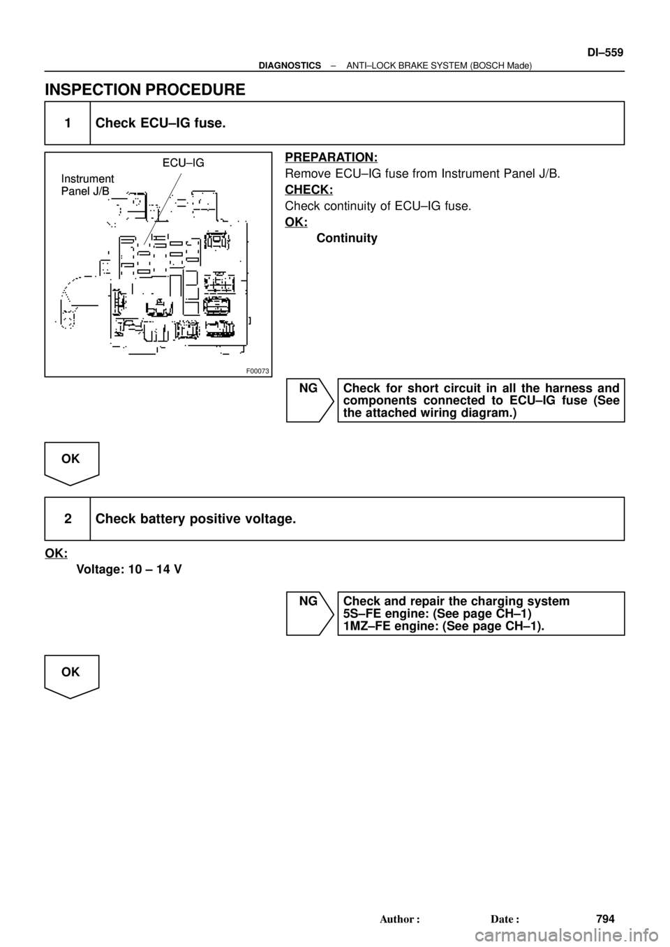
INSPECTION PROCEDURE
1 Check ECU±IG fuse.
PREPARATION:
Remove ECU±IG fuse from Instrument Panel J/B.
CHECK:
Check continuity of ECU±IG fuse.
OK:
Continuity
NG Check for short circuit in all the harness and
components connected to ECU±IG fuse (See
the attached wiring diagram.)
OK
2 Check battery positive voltage.
OK:
Voltage: 10 ± 14 V
NG Check and repair the charging system
5S±FE engine: (See page CH±1)
1MZ±FE engine: (See page CH±1).
OK

J23: (5S±FE)BRDLC2
34LG±R
BB
B J3ABS ECU
J8 J7
J/CJ/C
A19
EC
BRTc 8
LG±R
AA A BRII36
BR
311 DL")

J23: (5S±FE)
J/C
BRA
ABR
3
16 DLC1
Ts E
1
R±Y
II38
R±Y
A198
TsABS ECU
J22: (1MZ±FE)
J23: (5S±FE)
AB0119S08096
F")