Page 3167 of 4770
Airbag
Sensor
Assembly
PL+
PL±
(+)(±)
± DIAGNOSTICSSUPPLEMENTAL RESTRAINT SYSTEM
DI±747
982 Author�: Date�:
DTC B0136/74 Open in P/T Squib (LH) Circuit
CIRCUIT DES")
H01016H02141H02213
P/T Squib (LH)Airbag
Sensor
Assembly
PL+
PL±
(+)(±)
± DIAGNOSTICSSUPPLEMENTAL RESTRAINT SYSTEM
DI±747
982 Author�: Date�:
DTC B0136/74 Open in P/T Squib (LH) Circuit
CIRCUIT DESCRIPTION
The P/T squib circuit (LH) consists of the airbag sensor assembly and seat belt pretensioner (LH).
It causes the SRS to deploy when the SRS deployment conditions are satisfied.
For details of the function of each component, see OPERATION on page RS±2.
DTC B0136/74 is recorded when an open is detected in the P/T squib (LH) circuit.
DTC No.DTC Detecting ConditionTrouble Area
B0136/74
�Open circuit in PL+ wire harness or PL± wire harness of
squib
�P/T squib (LH) malfunction
�Airbag sensor assembly malfunction�Seat belt pretensioner (LH)
�Airbag sensor assembly
�Wire harness
WIRING DIAGRAM
See page DI±743.
INSPECTION PROCEDURE
1 Prepare for inspection. (See step 1 on page DI±787)
2 Check P/T squib (LH) circuit.
CHECK:
For the connector (on the seat belt pretensioner side) between
the seat belt pretensioner (LH) and the airbag sensor assembly,
measure the resistance between PL+ and PL±.
OK:
Resistance: Below 1 W
NG Repair or replace harness or connector be-
tween seat belt pretensioner (LH) and airbag
sensor assembly.
OK
DI1BJ±14
Page 3170 of 4770

Airbag
Sensor
Assembly
PL+
(+)
(±)
DI±750
± DIAGNOSTICSSUPPLEMENTAL RESTRAINT SYSTEM
985 Author�: Date�:
DTC B0137/71 Short in P/T Squib (LH) Circuit
(to Ground)")
H01016H08392H08396
P/T Squib (LH)
Airbag
Sensor
Assembly
PL+
(+)
(±)
DI±750
± DIAGNOSTICSSUPPLEMENTAL RESTRAINT SYSTEM
985 Author�: Date�:
DTC B0137/71 Short in P/T Squib (LH) Circuit
(to Ground)
CIRCUIT DESCRIPTION
The P/T squib (LH) circuit consists of the airbag sensor assembly and seat belt pretensioner (LH).
It causes the SRS to deploy when the SRS deployment conditions are satisfied.
For details of the function of each component, see OPERATION on page RS±2.
DTC B0137/71 is recorded when a ground short is detected in the P/T squib (LH) circuit.
DTC No.DTC Detecting ConditionTrouble Area
B0137/71
�Short circuit in P/T squib (LH) wire harness (to ground)
�P/T squib (LH) malfunction
�Airbag sensor assembly malfunction�Seat belt pretensioner (LH)
�Airbag sensor assembly
�Wire harness
WIRING DIAGRAM
See page DI±743.
INSPECTION PROCEDURE
1 Prepare for inspection. (See step 1 on page DI±787)
2 Check P/T squib (LH) circuit.
CHECK:
For the connector (on the seat belt pretensioner side) between
the seat belt pretensioner (LH) and the airbag sensor assembly,
measure the resistance between PL+ and body ground.
OK:
Resistance: 1 MW or Higher
NG Repair or replace harness or connector be-
tween seat belt pretensioner (LH) and airbag
sensor assembly.
OK
DI1BK±10
Page 3173 of 4770

PL+
(±) (+) ON
± DIAGNOSTICSSUPPLEMENTAL RESTRAINT SYSTEM
DI±753
988 Author�: Date�:
DTC B0138/72 Short in P/T Squib (LH) Circuit (to")
H01016AB0119
H08394H08269
Airbag
Sensor
Assembly P/T Squib (LH)
PL+
(±) (+) ON
± DIAGNOSTICSSUPPLEMENTAL RESTRAINT SYSTEM
DI±753
988 Author�: Date�:
DTC B0138/72 Short in P/T Squib (LH) Circuit (to B+)
CIRCUIT DESCRIPTION
The P/T squib (LH) circuit consists of the airbag sensor assembly and seat belt pretensioner (LH).
It causes the SRS to deploy when the SRS deployment conditions are satisfied.
For details of the function of each component, see OPERATION on page RS±2.
DTC B0138/72 is recorded when a B+ short is detected in the P/T squib (LH) circuit.
DTC No.DTC Detecting ConditionTrouble Area
B0138/72
�Short circuit in seat belt pretensioner (LH) wire harness
(to B+)
�P/T squib (LH) malfunction
�Airbag sensor assembly malfunction�Seat belt pretensioner (LH)
�Airbag sensor assembly
�Wire harness
WIRING DIAGRAM
See page DI±743.
INSPECTION PROCEDURE
1 Prepare for inspection. (See step 1 on page DI±787)
2 Check P/T squib (LH) circuit.
CHECK:
(a) Turn ignition switch to ON.
(b) For the connector (on the seat belt pretensioner side) be-
tween the seat belt pretensioner (LH) and the airbag sen-
sor assembly, measure the voltage between PL+ and
body ground.
OK:
Voltage: 0 V
NG Repair or replace harness or connector be-
tween seat belt pretensioner (LH) and airbag
sensor assembly.
OK
DI1BL±14
Page 3178 of 4770
H01450
Side Aribag Sensor Assembly (RH)
Airbag Sensor Assembly
GR
LG
L±Y
P ESR
FSR
SSR+
VUPR4
3
2
1C197
9
10
12ESR
FSR
SSR+
VUPR C19
C19
C19 DI±758
± DIAGNOSTICSSUPPLEMENTAL RESTRAINT SYSTEM
993 Author�: Date�:
DTC B1140/32 Side Airbag Sensor Assembly (RH)
Malfunction
CIRCUIT DESCRIPTION
The side airbag sensor assembly (RH) consists of the safing sensor, diagnosis circuit and lateral decelera-
tion sensor, etc.
It receives signals from the lateral deceleration sensor, judges whether or not the SRS must be activated,
and diagnosis system malfunction.
DTC B1140/32 is recorded when occurrence of a malfunction in the side airbag sensor assembly (RH) is
detected.
DTC No.DTC Detecting ConditionTrouble Area
B1140/32�Side airbag sensor assembly (RH) malfunction
�Side airbag sensor assembly (RH)
�Wire harness
�Airbag sensor assembly
WIRING DIAGRAM
DI4L8±01
Page 3186 of 4770
H01450
Side Airbag Sensor Assembly (LH)
Airbag Sensor Assembly
LG±B
L±W
P±L ESL
FSL
SSL+
VUPL4
3
2
1C1712
10
9
7 GR±L
ESL
FSL
SSL+
VUPL C17
C17
C17 DI±766
± DIAGNOSTICSSUPPLEMENTAL RESTRAINT SYSTEM
1001 Author�: Date�:
DTC B1141/33 Side Airbag Sensor Assembly (LH)
Malfunction
CIRCUIT DESCRIPTION
The side airbag sensor assembly (LH) consists of the safing sensor, diagnosis circuit and lateral deceleration
sensor, etc.
It receives signals from the lateral deceleration sensor, judges whether or not the SRS must be activated,
and diagnosis system malfunction.
DTC B1141/33 is recorded when occurrence of a malfunction in the side airbag sensor assembly (LH) is
detected.
DTC No.DTC Detecting ConditionTrouble Area
B1141/33�Side airbag sensor assembly (LH) malfunction
�Side airbag sensor assembly (LH)
�Wire harness
�Airbag sensor assembly
WIRING DIAGRAM
DI4L9±01
Page 3194 of 4770
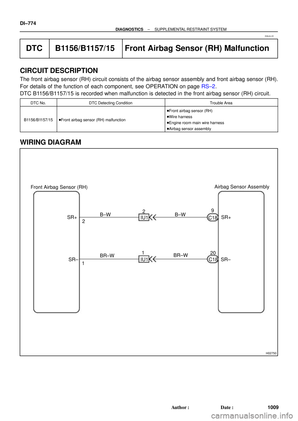
H02750
Airbag Sensor Assembly
Front Airbag Sensor (RH)
SR+
SR± C18
C189
20 B±W
BR±W IU12
1 B±W
BR±W 2
1 SR+
SR± IU1 DI±774
± DIAGNOSTICSSUPPLEMENTAL RESTRAINT SYSTEM
1009 Author�: Date�:
DTC B1156/B1157/15 Front Airbag Sensor (RH) Malfunction
CIRCUIT DESCRIPTION
The front airbag sensor (RH) circuit consists of the airbag sensor assembly and front airbag sensor (RH).
For details of the function of each component, see OPERATION on page RS±2.
DTC B1156/B1157/15 is recorded when malfunction is detected in the front airbag sensor (RH) circuit.
DTC No.DTC Detecting ConditionTrouble Area
B1156/B1157/15�Front airbag sensor (RH) malfunction
�Front airbag sensor (RH)
�Wire harness
�Engine room main wire harness
�Airbag sensor assembly
WIRING DIAGRAM
DI4LA±01
Page 3202 of 4770
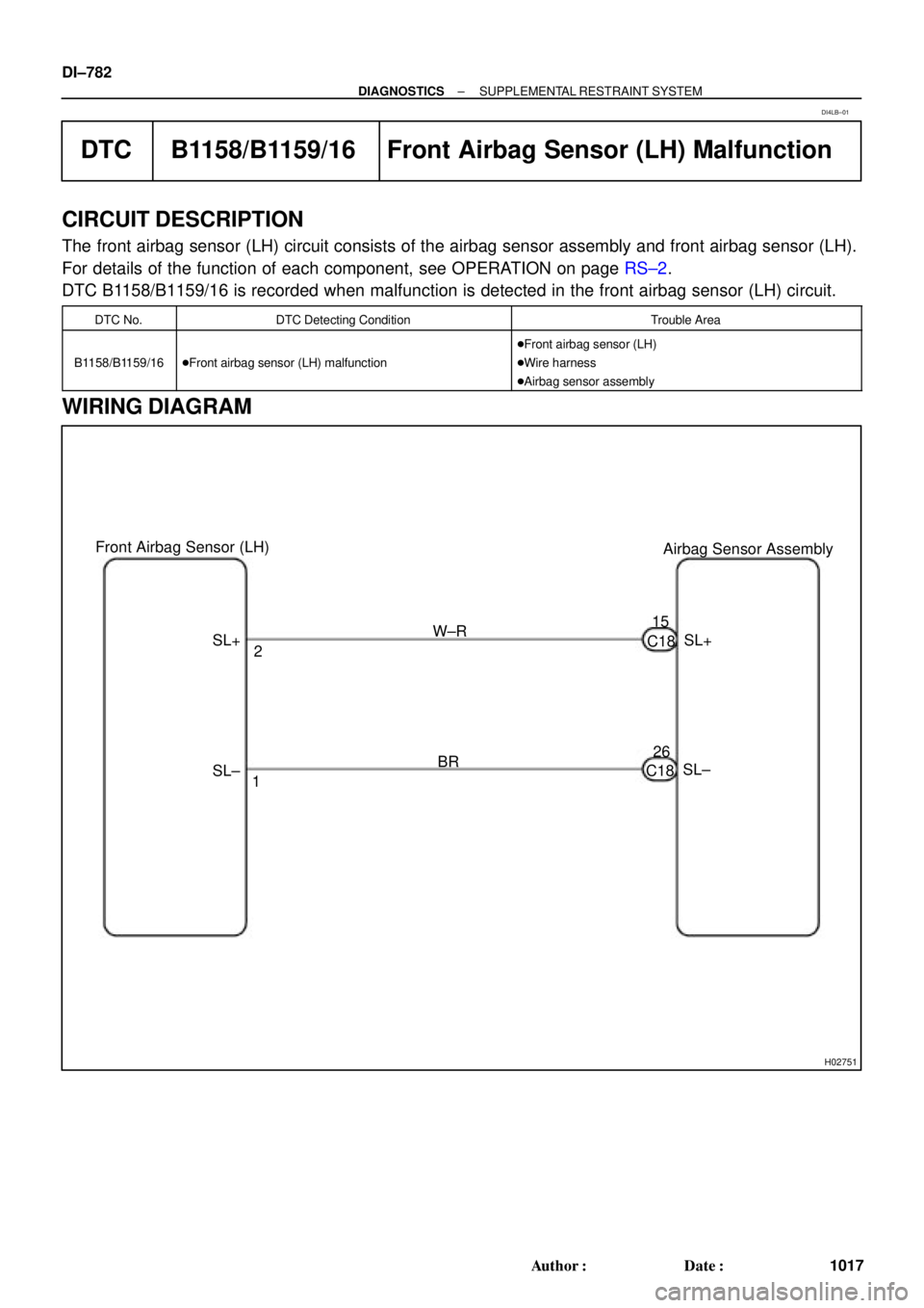
H02751
Airbag Sensor Assembly Front Airbag Sensor (LH)
SL+
SL± C1815
26 2
1 SL+W±R
BR
SL± C18 DI±782
± DIAGNOSTICSSUPPLEMENTAL RESTRAINT SYSTEM
1017 Author�: Date�:
DTC B1158/B1159/16 Front Airbag Sensor (LH) Malfunction
CIRCUIT DESCRIPTION
The front airbag sensor (LH) circuit consists of the airbag sensor assembly and front airbag sensor (LH).
For details of the function of each component, see OPERATION on page RS±2.
DTC B1158/B1159/16 is recorded when malfunction is detected in the front airbag sensor (LH) circuit.
DTC No.DTC Detecting ConditionTrouble Area
B1158/B1159/16�Front airbag sensor (LH) malfunction
�Front airbag sensor (LH)
�Wire harness
�Airbag sensor assembly
WIRING DIAGRAM
DI4LB±01
Page 3207 of 4770

H02288
15A CIG
L±R 2Airbag Sensor
Assembly 2
3 4
6 7
6
3B±R
65A IGN
C18 1K
IG 1K
1N1N
C18 Instrument Panel J/B
30A AM2
W±R W±R1
4 40A AM1
2L
1K2A
1B
1K1B
55 W2
1
2 Instrument Panel J/B
AF9 F4F6 FL MAIN
B±G
100A
ALT
Instrument Panel J/B Junction
Connector
W±B7
1J 1NW±BC18
1 Battery
1 1
2
5
B±O
GR
ACCIG2 Fusible Link Block
27
E1 Ignition Switch1 B±RB
± DIAGNOSTICSSUPPLEMENTAL RESTRAINT SYSTEM
DI±787
1022 Author�: Date�:
DTC Normal Source Voltage Drop
CIRCUIT DESCRIPTION
The SRS is equipped with a voltage±increase circuit (DC±DC converter) in the airbag sensor assembly in
case the source voltage drops.
When the battery voltage drops, the voltage±increase circuit (DC±DC converter) functions to increase the
voltage of the SRS to normal voltage.
The diagnosis system malfunction display for this circuit is different from other circuits that is when the SRS
warning light remains lit up and the DTC is a normal code, source voltage drop is indicated.
Malfunction in this circuit is not recorded in the airbag sensor assembly, and the source voltage returns to
normal, the SRS warning light automatically goes off.
DTC No.Diagnosis
(Normal)Source voltage drop
WIRING DIAGRAM
DI1BN±08

Airbag Sensor Assembly
GR
LG
L±Y
P ESR
FSR
SSR+
VUPR4
3
2
1C197
9
10
12ESR
FSR
SSR+
VUPR C19
C19
C19 DI±758
± DIAGNOSTICSSUPPLEMENTAL RESTRAINT SYSTEM
993 Au")

Airbag Sensor Assembly
LG±B
L±W
P±L ESL
FSL
SSL+
VUPL4
3
2
1C1712
10
9
7 GR±L
ESL
FSL
SSL+
VUPL C17
C17
C17 DI±766
± DIAGNOSTICSSUPPLEMENTAL RESTRAINT SYS")