Page 3282 of 4770

I08431
Theft Deterrent ECU
14
T4 Instrument Panel J/B
Door Unlock Detection
Switch Front LHJ6
J/C
L±RLSWD
LSWP
LSWR 15
T4
16
T4 L±R L±R11
IE1F F
W±B*1
IE
4
*1
1*21*1
4*2
J10E 4 1
W±B*1
J38
J/C
A A 20
IE1
W 7
1G 3
1V
W±B
W±B
*2
J37
J/C
C C
Y Y Y11
IM1 Door Unlock Detection
Switch Front RH
W±B
*1W±B*1
J39
J/C
A A
W±B
*2
20
IM1
W±B
IJ
L±Y J10EJ/C
L±Y
L±Y
L±Y
2
IF2 4
BO1 41 Door Unlock Detection
Switch Rear LH
Door Unlock Detection
Switch Rear RH W±B W±B6
BO1 A J40
J/C
BL
BN
IK
J9DL±Y L±Y
L±YW±B W±B
W±B W±B3
IN2 4
BP1 41 6
BP1
*1: TMC Made
*2: TMMK Made DI±862
± DIAGNOSTICSTHEFT DETERRENT SYSTEM
1097 Author�: Date�:
Door Unlock Detection Switch Circuit
CIRCUIT DESCRIPTION
The door unlock detection switch is built in the door lock motor assembly. This switch is ON when the door
lock knob is in the unlock position and OFF when the lock knob is in the lock position. The ECU detects the
door lock knob conditions in this circuit. It is used as one of the operating conditions for the key confinement
prevention function.
WIRING DIAGRAM
DI074±06
Page 3284 of 4770
I04444
Theft Deterrent ECU
DSWD
CTY
DSWP
4
T4
T4
T41
5 R±G A
J10 C
R±G 1
1G 7
1S
Integration
Relay
4
1G R±G
Door Courtesy
Switch Front LH
1
R±W J/C
E
J34 D
J33
D
J33
D J33 6
4
12
1S R±B
1 Door Courtesy
Switch Rear LH
J9
R±W
R±W 8
IN2 R±W
1 Door Courtesy
Switch Rear RH
R±W
1
Diode
2
R±G J/C
E
J33
J34D
E
J33R±G R±G
IN26
R±G
1 Door Courtesy
Switch Front RH
J/C
Instrument panel J/B DI±864
± DIAGNOSTICSTHEFT DETERRENT SYSTEM
1099 Author�: Date�:
Door Courtesy Switch Circuit
CIRCUIT DESCRIPTION
The door courtesy switch goes ON when the door is opened and goes OFF when the door is closed.
WIRING DIAGRAM
DI075±06
Page 3286 of 4770
I00257
Theft Deterrent ECU
DSWH
T33
B IG31
B 3
B 1 Engine Hood Courtesy
Switch
2
W±B
EBIK1 DI±866
± DIAGNOSTICSTHEFT DETERRENT SYSTEM
1101 Author�: Date�:
Engine Hood Courtesy Switch Circuit
CIRCUIT DESCRIPTION
The engine hood courtesy switch is built into the engine hood lock assembly and goes ON when the engine
hood is opened and goes OFF when the engine hood is closed.
WIRING DIAGRAM
DI076±06
Page 3301 of 4770
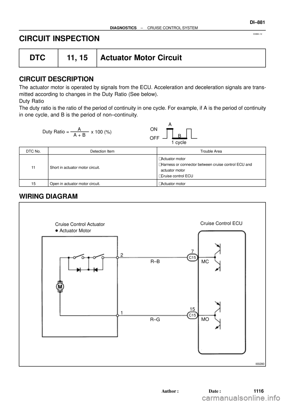
DI08M±12
Duty Ratio =A + BA
x 100 (%)
ON
OFFA
B
1 cycle
I00280
Cruise Control ECU
MC 7
MO R±B Cruise Control Actuator
� Actuator Motor
R±G 1 2
15
C15 C15
± DIAGNOSTICSCRUISE CONTROL SYSTEM
DI±881
111 6 Author�: Date�:
CIRCUIT INSPECTION
DTC 11, 15 Actuator Motor Circuit
CIRCUIT DESCRIPTION
The actuator motor is operated by signals from the ECU. Acceleration and deceleration signals are trans-
mitted according to changes in the Duty Ratio (See below).
Duty Ratio
The duty ratio is the ratio of the period of continuity in one cycle. For example, if A is the period of continuity
in one cycle, and B is the period of non±continuity.
DTC No.Detection ItemTrouble Area
11Short in actuator motor circuit.
�Actuator motor
�Harness or connector between cruise control ECU and
actuator motor
�Cruise control ECU
15Open in actuator motor circuit.�Actuator motor
WIRING DIAGRAM
Page 3303 of 4770

I00281
Cruise Control ECU
C15
G±B
2 1 34W±B
3
STOP Fuse8 Stop Light Switch
4
R±Y
Stop Lights Cruise Control Actuator
� Actuator Magnetic Clutch
J7
J7AAJ/C
W±B
1J
1J
W±B
A
J/C
IG 8
7
J11Instrument
Panel J/BL
± DIAGNOSTICSCRUISE CONTROL SYSTEM
DI±883
111 8 Author�: Date�:
DTC 12 Actuator Magnetic Clutch Circuit
CIRCUIT DESCRIPTION
This circuit turns on the magnetic clutch inside the actuator during cruise control operation according to the
signal from the ECU. If a malfunction occurs in the actuator or speed sensor, etc. during cruise control opera-
tion, the rotor shaft between the motor and control plate is released.
When the brake pedal is depressed, the stop light switch turns on, supplying electrical power to the stop light.
Power supply to the magnetic clutch is mechanically cut and the magnetic clutch is turned OFF.
When driving downhill, if the vehicle speed exceeds the set speed by 15 km/h (9 mph), the ECU turns the
safety magnet clutch OFF. If the vehicle speed later drops to within 10 km/h (6 mph), cruise control at the
set speed is resumed.
DTC No.Detection ItemTrouble Area
12Short in actuator magnetic clutch circuit.
Open (0.8 sec.) in actuator magnetic clutch circuit.
�STOP Fuse
�Stop light switch
�Actuator magnetic clutch
�Harness or connector between cruise control ECU and
actuator magnetic clutch, actuator magnetic clutch and body
ground
�Cruise control ECU
WIRING DIAGRAM
DI08N±12
Page 3306 of 4770
I00055
4
3(+)
(±)
DI±886
± DIAGNOSTICSCRUISE CONTROL SYSTEM
1121 Author�: Date�:
DTC 14 Actuator Mechanical Malfunction
CIRCUIT DESCRIPTION
The circuit detects the rotation position of the actuator control plate and sends a signal to the ECU.
DTC No.Detection ItemTrouble Area
14Cruise control actuator mechanical malfunction.
�Actuator lock: (motor, arm)
�Actuator motor
�Cruise control ECU
WIRING DIAGRAM
See page DI±881.
INSPECTION PROCEDURE
1 Check cruise control actuator arm locking operation
PREPARATION:
(a) Turn ignition switch OFF.
(b) Disconnect the actuator connector.
CHECK:
Connect the positive (+) lead from the battery to the terminal 3
of actuator and the negative (±) lead to terminal 4.
NOTICE:
Do not connect the high tension cables to the wrong bat-
tery terminal. The cruise control actuator will be damaged.
Move the control plate by hand.
OK:
Control plate doesn't move.
NG Replace cruise control actuator.
OK
DI08O±12
Page 3308 of 4770

I00292
Vehicle Speed Sensor
ECUCombination Meter
Cruise Control ECU
4 pulses/
1 rotation
of rotor shaft4 pulses/
1 rotation
of rotor shaft
I00282
Cruise Control ECU
12
SPDV±W V±WB
BJ15
J/CIG3
3
V±W14
Combination Meter
15
6
Speedo
±meter
P L
IJ12IJ17
P
3L
2
SI
SE
IG+
1
R±Lto GAUGE Fuse
C15
C9 C9
C10
Speed
Sensor DI±888
± DIAGNOSTICSCRUISE CONTROL SYSTEM
1123 Author�: Date�:
DTC 21 Open in Vehicle Speed Sensor Circuit
CIRCUIT DESCRIPTION
The signal from the vehicle speed sensor circuit is sent to cruise control ECU as vehicle speed signal.
The rotor shaft is driven by the gear of the transmission.
For each rotation of the shaft, the vehicle speed sensor sends a 4±pulse signal through the combination
meter to the cruise control ECU (See the following installation).
This signal is converted inside the combination meter and sent as a 4±pulse signal to the cruise control ECU.
The ECU calculates the vehicle speed from this pulse frequency.
DTC No.Detection ItemTrouble Area
21Speed signal is not input to the cruise control ECU while cruise
control is set.
�Combination meter
�Harness or connector between cruise control ECU and com-
bination meter, combination meter and vehicle speed sensor
�Vehicle speed sensor
�Cruise control ECU
WIRING DIAGRAM
DI08P±12
Page 3311 of 4770
± DIAGNOSTICSCRUISE CONTROL SYSTEM
DI±891
1126 Author�: Date�:
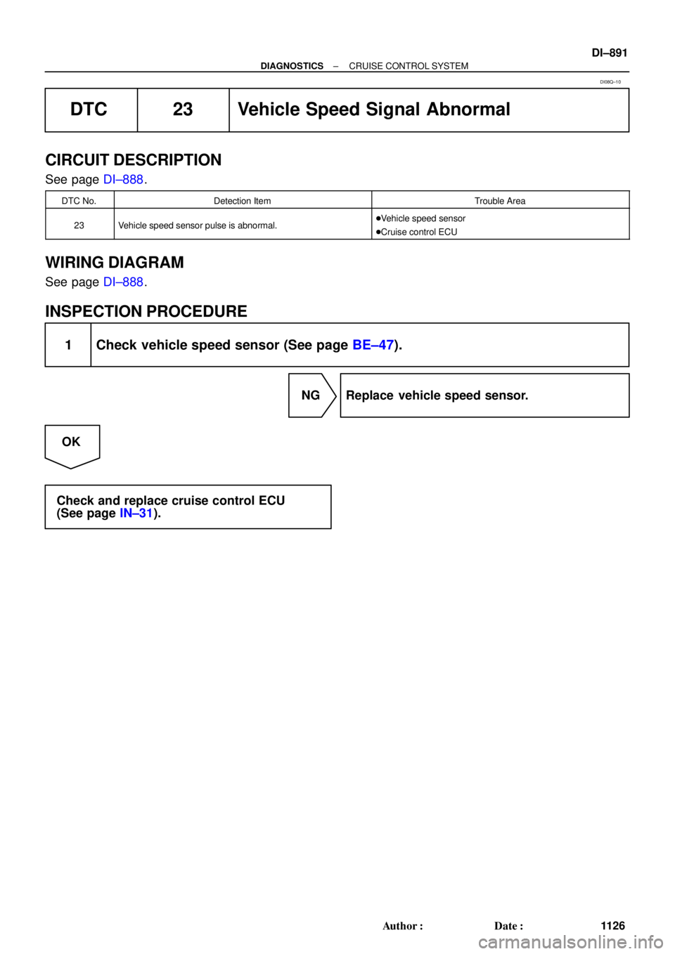
DTC 23 Vehicle Speed Signal Abnormal
CIRCUIT DESCRIPTION
See page DI±888.
DTC No.Detection ItemTrouble Area
23Vehicle speed sensor pulse is abnormal.�Vehicle speed sensor
�Cruise control ECU
WIRING DIAGRAM
See page DI±888.
INSPECTION PROCEDURE
1 Check vehicle speed sensor (See page BE±47).
NG Replace vehicle speed sensor.
OK
Check and replace cruise control ECU
(See page IN±31).
DI08Q±10