Page 3334 of 4770
I00290
Cruise Control ECU
4
PI
O D DJ/C
O IG25
O 10
7
R±L D DJ/C
R±L
Instrument Panel J/B
2
1D
1K1
B±Y4IG1AM1 Ignition Switch
2
W
Instrument Panel J/B
AM1 GAUGE
2
1K 1
1B
B±R 1
ALT FL BLOCK
1
B±G
FL MAIN
BatteryCRUISE MAIN
Indicator Light
(in Combination Meter)
C15
J2
C10
C10 J4
F9
F4 DI±914
± DIAGNOSTICSCRUISE CONTROL SYSTEM
1149 Author�: Date�:
CRUISE MAIN Indicator Light Circuit
CIRCUIT DESCRIPTION
When the cruise control main switch is turned ON, CRUISE MAIN indicator light lights up.
WIRING DIAGRAM
DI090±17
Page 3336 of 4770
I00291
Cruise Control ECU
4
PI
5
TC O
LG±R D DJ/C
J/C
B
B B O
LG±R 10
4DLC2
II3 11
C15
LG±R*1
11 DLC1
C15
J2
D4 D4
J3
D1LG±R
P±B
*2
*1: TMC Made, TMMK Made (5S±FE)
*2: TMMK Made (1MZ±FE) DI±916
± DIAGNOSTICSCRUISE CONTROL SYSTEM
1151 Author�: Date�:
Diagnosis Circuit
CIRCUIT DESCRIPTION
This circuit sends a signal to the ECU that outputs DTC.
WIRING DIAGRAM
DI091±11
Page 3349 of 4770
I08435
ECM
E10 28
93
E10
E10 3
4G±W
R±L
L±Y Transponder Key Amplifier
CODE
RXCK
TXCT 5S±FE engine:
G±W
R±L
L±Y 1
II4
4
II4
2
II4
± DIAGNOSTICSENGINE IMMOBILISER SYSTEM
DI±929
1164 Author�: Date�:
DTC B2796/99 No Communication in Immobiliser system
CIRCUIT DESCRIPTION
DTC No.DTC Detecting ConditionTrouble Area
B2796/99No communication
�Key
�Transponder Key Coil
�Transponder Key Amplifier
�Wireharness
�ECM
WIRING DIAGRAM
DI4FF±01
Page 3352 of 4770
I08435
ECM
E10 28
93
E10
E10 3
4G±W
R±L
L±Y Transponder Key Amplifier
CODE
RXCK
TXCT 5S±FE engine:
G±W
R±L
L±Y 1
II4
4
II4
2
II4 DI±932
± DIAGNOSTICSENGINE IMMOBILISER SYSTEM
1167 Author�: Date�:
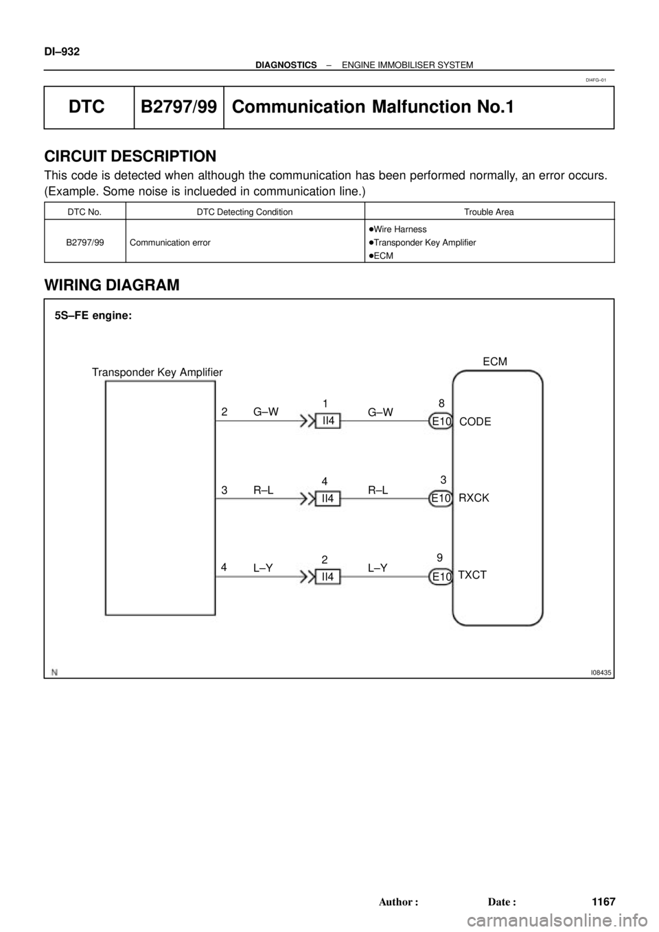
DTC B2797/99 Communication Malfunction No.1
CIRCUIT DESCRIPTION
This code is detected when although the communication has been performed normally, an error occurs.
(Example. Some noise is inclueded in communication line.)
DTC No.DTC Detecting ConditionTrouble Area
B2797/99Communication error
�Wire Harness
�Transponder Key Amplifier
�ECM
WIRING DIAGRAM
DI4FG±01
Page 3355 of 4770
I08435
ECM
E10 28
93
E10
E10 3
4G±W
R±L
L±Y Transponder Key Amplifier
CODE
RXCK
TXCT 5S±FE engine:
G±W
R±L
L±Y 1
II4
4
II4
2
II4
± DIAGNOSTICSENGINE IMMOBILISER SYSTEM
DI±935
1170 Author�: Date�:
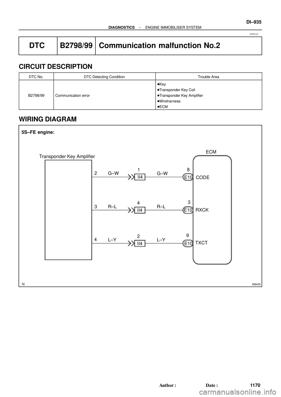
DTC B2798/99 Communication malfunction No.2
CIRCUIT DESCRIPTION
DTC No.DTC Detecting ConditionTrouble Area
B2798/99Communication error
�Key
�Transponder Key Coil
�Transponder Key Amplifier
�Wireharness
�ECM
WIRING DIAGRAM
DI4FH±01
Page 3700 of 4770

V08423 Knock Sensor 1
GRECM
KNK
E1 12
E6
WIRING DIAGRAM
Wiring Diagram
This shows a wiring diagram of the circuit.
Use this diagram together with ELECTRICAL
WIRING DIAGRAM to thoroughly understand the
circuit.
Wire colors are indicated by an alphabetical code.
B = Black, L = Blue, R = Red, BR = Brown,
LG = Light Green, V = Violet, G = Green,
O = Orange, W = White, GR = Gray, P = Pink,
Y = Yellow, SB = Sky Blue
The first letter indicates the basic wire color and
the second letter indicates the color of the stripe.
DTC P0325Knock Sensor 1 Circuit Malfunction
CIRCUIT DESCRIPTION
Knock sensor is fitted to the cylinder block to detect engine knocking. This sensor contains a piezoelectric element which
generates a voltage when it becomes deformed, which occurs when the cylinder block vibrates due to knocking. If engine
knocking occurs, ignition timing is retarded to suppress it.
DTC No. DTC Detecting Condition Trouble Area
P0325No knock sensor 1 signal to ECM with engine speed,
1,200 rpm or more.� Open or short in knock sensor1 circuit
� Knock sensor 1 (looseness)
� ECM
If the ECM detects the above diagnosis conditions, it operates the fall safe function in which the corrective retard angle
value is set to the maximum value.
� Diagnostic Trouble Code No. and Detection Item
� Circuit Description
The major role and operation, etc. of the circuit
and its component parts are explained.
� Indicates the diagnostic trouble code, diagnostic
trouble code set parameter and suspect area of
the problem.
�
± INTRODUCTIONHOW TO TROUBLESHOOT ECU CONTROLLED
SYSTEMSIN±29
29 Author�: Date�:
6. CIRCUIT INSPECTION
How to read and use each page is shown below.
Page 4498 of 4770

SLIDING ROOF DIAGNOSTIC TIPS ± BO020-01 August 17, 2001
Page 5 of 7
�The recommended sliding roof removal and disassembly procedure is provided in the
2001 Camry Repair Manual, pages BO±62 through BO±65. Take time to read the
procedure before disassembling the sliding roof assembly.
�When the system is diagnosed and the failed part is identified, the failed part can be
removed by following the disassembly procedure in the 2001 Camry Repair Manual
pages BO±66 through BO±67. Adjustment information is available on pages BO±68
and BO±69.
�Electrical diagnosis information can be found:
�2001 Camry Repair Manual, pages BE±89 through BE±92.
�2001 Camry Electrical Wiring Diagram, pages 168 through 170.
The following service tips are not provided in the Repair Manuals:
Drain Tube Function
�To clear clogs in the drain tubes,
insert a long speedometer cable.
�A long speedometer cable can be
inserted into each drain, to
determine if the drain tubes are
exiting to the ground instead of
inside the vehicle.
�Do NOT blast air down the tube
because this can cause the drain
tube to become disconnected
from the sliding roof.
Guide Pin Adjustment
�Adjustments are noted in the
2001 Camry Repair Manual,
page BO±69.
�In addition, when the guide pin
roller moves up and down, the Lift
Arm should be able to move
forward±backward a distance of
0.6 mm +/± 0.2 mm.Service Tips
Move Forward
0.6 mm +/± 0.2 mm
Down
Page 4619 of 4770

Toyota Supports ASE CertificationPage 1 of 4
PG001-03Title:
REPAIR MANUAL CORRECTIONS INDEX
Models:
All ModelsTechnical Service
BULLETIN
February 28, 2003
Corrections have been made in the repair manuals listed below. Corrections available
in the last quarter are marked in red. The Toyota Technical Information system (TIS) is
the best way to access up±to±date service information.
NOTE:
When ordering a technical publication (i.e., Repair Manual, Electrical Wiring Diagram)
from the MDC, any Correction Page(s) associated with that particular Publication will
automatically be included with your order.
Correction Pages are available through the Dealer Support Material Network (MDC NPM
System) via the corresponding part numbers from the following table.
Publication Number Page(s) Part Number
2003 4Runner RM1001±U1 03±36 00400±RM100±12131. . . . . . . . . . . . . . . . . . . . . . . .
RM1001±U2 29±6O . . . . . . . . . . . . . . . . . . . . . . . . . . . . . . . . . . . . . . . . . . . . . . . . . . . . . . . . . .
29±23O . . . . . . . . . . . . . . . . . . . . . . . . . . . . . . . . . . . . . . . . . . . . . . . . . . . . . . . . . . . . . . . . . . . . . .
25±18 00400±RM100±22146 . . . . . . . . . . . . . . . . . . . . . . . . . . . . . . . . . . . . . . . . . . . . . . . . . . .
26±3O . . . . . . . . . . . . . . . . . . . . . . . . . . . . . . . . . . . . . . . . . . . . . . . . . . . . . . . . . . . . . . . . . . . . . . .
26±17O . . . . . . . . . . . . . . . . . . . . . . . . . . . . . . . . . . . . . . . . . . . . . . . . . . . . . . . . . . . . . . . . . . . . . .
27±6O . . . . . . . . . . . . . . . . . . . . . . . . . . . . . . . . . . . . . . . . . . . . . . . . . . . . . . . . . . . . . . . . . . . . . . .
27±9O . . . . . . . . . . . . . . . . . . . . . . . . . . . . . . . . . . . . . . . . . . . . . . . . . . . . . . . . . . . . . . . . . . . . . . .
27±29O . . . . . . . . . . . . . . . . . . . . . . . . . . . . . . . . . . . . . . . . . . . . . . . . . . . . . . . . . . . . . . . . . . . . . .
27±31O . . . . . . . . . . . . . . . . . . . . . . . . . . . . . . . . . . . . . . . . . . . . . . . . . . . . . . . . . . . . . . . . . . . . . .
27±32O . . . . . . . . . . . . . . . . . . . . . . . . . . . . . . . . . . . . . . . . . . . . . . . . . . . . . . . . . . . . . . . . . . . . . .
27±34O . . . . . . . . . . . . . . . . . . . . . . . . . . . . . . . . . . . . . . . . . . . . . . . . . . . . . . . . . . . . . . . . . . . . . .
27±36O . . . . . . . . . . . . . . . . . . . . . . . . . . . . . . . . . . . . . . . . . . . . . . . . . . . . . . . . . . . . . . . . . . . . . .
27±37O . . . . . . . . . . . . . . . . . . . . . . . . . . . . . . . . . . . . . . . . . . . . . . . . . . . . . . . . . . . . . . . . . . . . . .
RM1001±U1 05±614 to 05±616 00400±RM100±12156 . . . . . . . . . . . . . . . . . . . . . . . . . . .
05±712O . . . . . . . . . . . . . . . . . . . . . . . . . . . . . . . . . . . . . . . . . . . . . . . . . . . . . . . . . . . . . . . . . . . .
05±713O . . . . . . . . . . . . . . . . . . . . . . . . . . . . . . . . . . . . . . . . . . . . . . . . . . . . . . . . . . . . . . . . . . . .
05±713±1 to 05±713±7O . . . . . . . . . . . . . . . . . . . . . . . . . . . . . . . . . . . . . . . . . . . . . . . . . . . . . .
05±724 to 05±737O . . . . . . . . . . . . . . . . . . . . . . . . . . . . . . . . . . . . . . . . . . . . . . . . . . . . . . . . . . .
05±811 to 05±813O . . . . . . . . . . . . . . . . . . . . . . . . . . . . . . . . . . . . . . . . . . . . . . . . . . . . . . . . . . .
PRODUCT GENERAL INFORMATION
Introduction
Parts
Information
4Runner


*2: TMMK Made (1MZ±FE) DI±91")