Page 3267 of 4770

*1
Daytime Running
Light Relay*2
Dayti")
I08428
E/G Room J/B No.2
Theft Deterrent ECU Headlight
Control Realy
FL MAIN
Battery 3
2BMAIN
HEAD R±B B
3 4
1
28
2K
32G
1
F61
F4Light Control Switch
(COMB. SW)
*1
Daytime Running
Light Relay*2
Daytime Running
Light Relay7
IG310
T3 R±B
*1
R±B*2R*2
19J32
*1
J6*2
J/C
*1: w/o Daytime Running Light
*2: w/ Daytime Running Light2BB
FL BLOCK
B±GR±B
± DIAGNOSTICSTHEFT DETERRENT SYSTEM
DI±847
1082 Author�: Date�:
Headlight Control Relay Circuit
CIRCUIT DESCRIPTION
When the theft deterrent system is activated, it causes the Tr in the ECU to switch ON and OFF at approxi-
mately 0.4 sec. intervals. This switches the headlight control relay ON and OFF, thus flashing the headlights
(See the wiring diagram below).
In this condition, if any of the following operations is done, the Tr in the ECU goes OFF and the headlight
control relay switches OFF, thus stopping the headlights flashing:
(1) Unlock the front LH or RH door with key.
(2) Turn the ignition switch to ACC or ON position.
(3) Unlock the doors with the wireless door lock control system.
(4) Wait for approximately 60 seconds.
(5) Push the panic switch of the wireless door lock control system.
WIRING DIAGRAM
DI06X±06
Page 3269 of 4770

I00266
Theft Deterrent ECU
TAIL
T3
11
G±R
B BJ/C J33
G±R
10
IG1
G±RA
AJ2
J/C
G±R 1C
6
2
3
Taillight Control Relay
1
5
TAIL81S
1C
9
1B
4 Instrument Panel J/B
B±R
Light
Failure
Sensor
Turn & Clearance
Light
1F9
F4
1
FL
BLOCK
FL MAIN
Battery
B±G ALT
± DIAGNOSTICSTHEFT DETERRENT SYSTEM
DI±849
1084 Author�: Date�:
Taillight Control Relay Circuit
CIRCUIT DESCRIPTION
When the theft deterrent system is activated, it causes the Tr in the ECU to switch ON and OFF at approxi-
mately 0.4 sec. intervals. This switches the taillight control relay ON and OFF, thus flashing the taillights (See
the wiring diagram below).
In this condition, if any of the following operations is done, the Tr in the ECU goes OFF and the taillight control
relay switches OFF, thus stopping the taillights flashing:
(1) Unlock the front LH or RH door with key.
(2) Turn the ignition switch to ACC or ON position.
(3) Unlock the doors with the wireless door lock control system.
(4) Wait for approximately 60 seconds.
(5) Push the panic switch of the wireless door lock control system.
WIRING DIAGRAM
DI06Y±06
Page 3271 of 4770
I01927
Theft Deterrent ECU
T4
13
IG B±R B
J17
C
J16B±R Instrument Panel J/B
8
1
ECU±IG
1
1B AM1
2
1K
4 B±Y AM1
2Ignition Switch
W
B±R
B±R 1
F9 ALT
FL BLOCK
F4
1
B±G
FL MAIN
Battery
1D
1K
IG1
± DIAGNOSTICSTHEFT DETERRENT SYSTEM
DI±851
1086 Author�: Date�:
Ignition Switch Circuit
CIRCUIT DESCRIPTION
When the ignition switch is turned to the ACC position, battery positive voltage is applied to the terminal ACC
of the ECU. Also, if the ignition switch is turned to the ON position, battery positive voltage is applied to the
terminals ACC and IG of the ECU. When the battery positive voltage is applied to the terminal ACC of the
ECU while the theft deterrent system is activated, the warning stops. Furthermore, power supplied from the
terminals ACC and IG of the ECU is used as power for the door courtesy switch, and position switch, etc.
WIRING DIAGRAM
DI06Z±06
Page 3272 of 4770
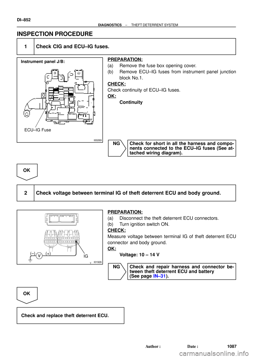
I00269
Instrument panel J/B:
ECU±IG Fuse
I01926
IG (+) (±)
DI±852
± DIAGNOSTICSTHEFT DETERRENT SYSTEM
1087 Author�: Date�:
INSPECTION PROCEDURE
1 Check CIG and ECU±IG fuses.
PREPARATION:
(a) Remove the fuse box opening cover.
(b) Remove ECU±IG fuses from instrument panel junction
block No.1.
CHECK:
Check continuity of ECU±IG fuses.
OK:
Continuity
NG Check for short in all the harness and compo-
nents connected to the ECU±IG fuses (See at-
tached wiring diagram).
OK
2 Check voltage between terminal IG of theft deterrent ECU and body ground.
PREPARATION:
(a) Disconnect the theft deterrent ECU connectors.
(b) Turn ignition switch ON.
CHECK:
Measure voltage between terminal IG of theft deterrent ECU
connector and body ground.
OK:
Voltage: 10 ± 14 V
NG Check and repair harness and connector be-
tween theft deterrent ECU and battery
(See page IN±31).
OK
Check and replace theft deterrent ECU.
Page 3273 of 4770
I08429
Instrument Panel J/B Key Unlock
Warning SwitchTheft Deterrent ECU
W±B6
KSW
L±BT4 B
J9 B
J9J/C
L±B
L±B
A
J11
J/C
IG W±B 7
1J 3
1M 215
1M7
1D
Instrument Panel J/B
± DIAGNOSTICSTHEFT DETERRENT SYSTEM
DI±853
1088 Author�: Date�:
Key Unlock Warning Switch Circuit
CIRCUIT DESCRIPTION
The key unlock warning switch goes ON when the ignition key is inserted in the key cylinder and goes OFF
when the ignition key is removed.
The ECU operates the key confinement prevention function while the key unlock warning switch is ON.
WIRING DIAGRAM
DI070±06
Page 3275 of 4770
I00252
Theft Deterrent ECU
LUG 7
T4G±W C CJ33
J/C
G±W 2IF1G±W 2 1 Luggage Compartment
Door Key Lock and
Unlock Switch
BP
W±B
± DIAGNOSTICSTHEFT DETERRENT SYSTEM
DI±855
1090 Author�: Date�:
Luggage Compartment Door Key Lock and Unlock Switch Circuit
CIRCUIT DESCRIPTION
The luggage compartment door key lock and unlock switch goes ON when the luggage compartment door
key cylinder is turned to the unlock side with the key.
WIRING DIAGRAM
DI071±04
Page 3278 of 4770
I00253
Theft Deterrent ECU
DSWL
T42
R±Y 6
IF1
R±Y
1
Luggage Compartment
Door Courtesy Switch DI±858
± DIAGNOSTICSTHEFT DETERRENT SYSTEM
1093 Author�: Date�:
Luggage compartment Door Courtesy Switch Circuit
CIRCUIT DESCRIPTION
The luggage compartment door courtesy switch goes ON when luggage compartment door is opened and
goes off when the luggage compartment door is closed.
WIRING DIAGRAM
DI072±06
Page 3280 of 4770
I08430
Door Key Lock and
Unlock Switch RH Instrument Panel J/BTheft Deterrent ECU
B9
UL3 J6
J/C Door Key Lock and
Unlock Switch LH
L2 T4
8
T4
UL2 10
T4 B 3
IE1
L±W UNLOCK
R±G R±G R±G
4
IE1
L±WL±W BB 3
2
LOCK J38
J/C
AA1
W±B
*1
IE W±BW±B
*1
20
IE1
7
1G3
1V
W±B
J37
J/C
L±W L±W4
IM1
3
IM1B 2
3AA
L L
L LOCK
UNLOCK
IJ20
IM1J39
J/C
AA1
W±B
*1W±B*1
W±B*2
W±B*2*1: TMC Made
*2: TMMK Made W±B DI±860
± DIAGNOSTICSTHEFT DETERRENT SYSTEM
1095 Author�: Date�:
Door Key Lock and Unlock Switch Circuit
CIRCUIT DESCRIPTION
The door key lock and unlock switch is built in the door key cylinder. When the key is turned to the lock side,
terminal 1 of the switch is grounded and when the key is turned to the unlock side, terminal 2 of the switch
is grounded.
WIRING DIAGRAM
DI073±06