Page 3239 of 4770
I00224
Wireless Door Lock ECU
Key Unlock
Warning
SwitchKSW L±B
W±B
1M1J7 5 5
1
2
3 7
IG10
1D
J/C L±B
W±B1M
Integration Relay
Instrument Panel J/BW6 J10 Instrument Panel J/B
L±B B
J9B
J11
A
± DIAGNOSTICSWIRELESS DOOR LOCK CONTROL SYSTEM
DI±819
1054 Author�: Date�:
Key Unlock Warning Switch Circuit
CIRCUIT DESCRIPTION
When the key is inserted in the ignition key cylinder, the key unlock warning switch comes ON, and when
the key is not inserted the switch is OFF.
When the key unlock warning switch is ON, the ECU operates the key confinement prevention function.
WIRING DIAGRAM
DI05V±03
Page 3241 of 4770
I00223
Wireless Door
Lock ECU Theft Deterrent
ECU
Integration Relay
Door Cour-
tesy Switch R±W
R±G DSWD
CTY
DSWPR±WIN2 1G
1S J10 J9
J33 J34
ED A 4
4
6
Rear RH
Rear LHFront RH
Front LH8 1S1G R±G R±G
R±GR±W
R±G R±W R±W
4
CTY
5
6 1C
14
1
2 712
11 11 R±W J33J33
J34D
DE
R±G
J33
J33
J34 DE
ER±W
T4W6 T4
T4
IN2R±G Instrument Panel J/B
1
± DIAGNOSTICSWIRELESS DOOR LOCK CONTROL SYSTEM
DI±821
1056 Author�: Date�:
Door Courtesy Switch Circuit
CIRCUIT DESCRIPTION
The door courtesy switch comes ON when the door is opened and goes OFF when door is closed. Further-
more. the door courtesy switch circuit has terminal +B connected inside the theft deterrent ECU . Battery
positive voltage is applied to terminal DSWD of the theft deterrent ECU when all doors are closed, i.e., when
the door courtesy switches of all doors are OFF.
WIRING DIAGRAM
DI05W±03
Page 3243 of 4770
I00301
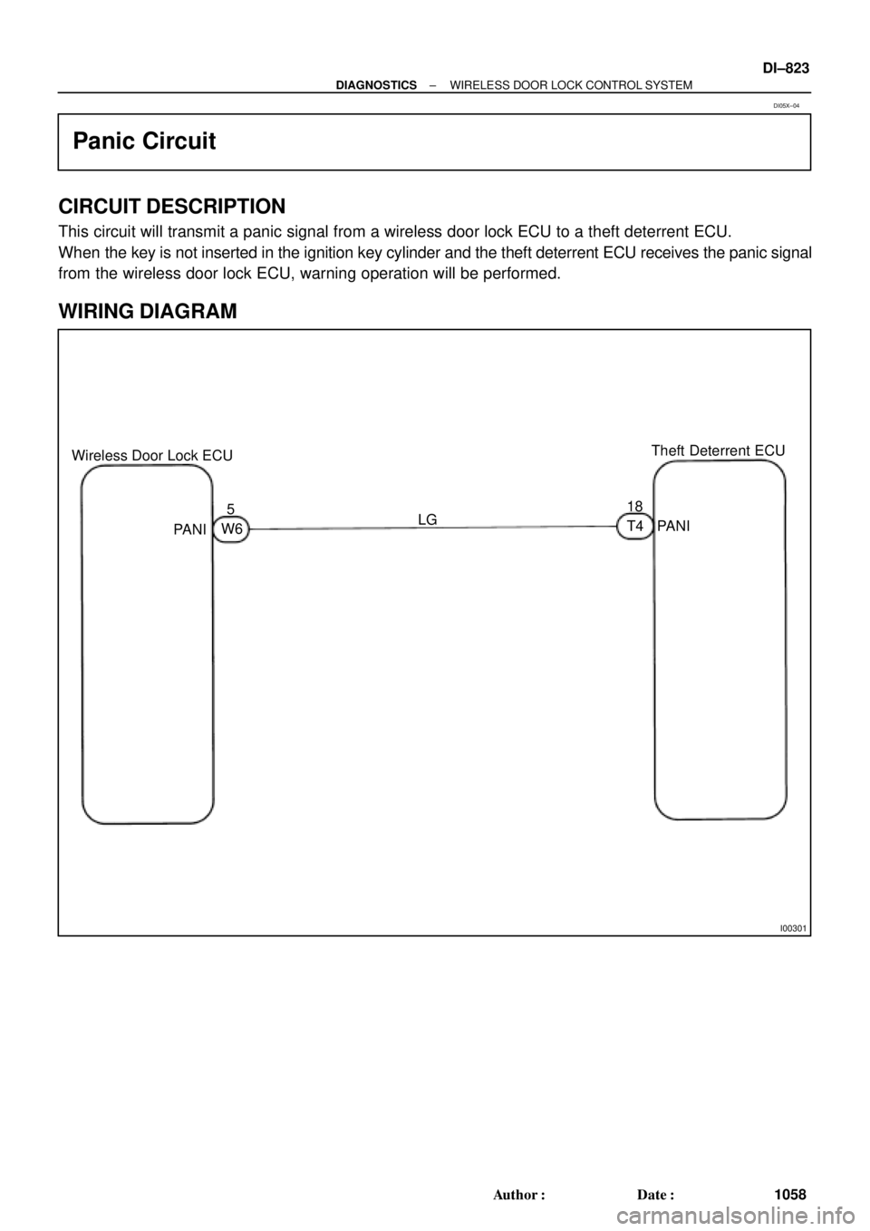
Wireless Door Lock ECUTheft Deterrent ECU
518
LG
PANI
PANIW6T4
± DIAGNOSTICSWIRELESS DOOR LOCK CONTROL SYSTEM
DI±823
1058 Author�: Date�:
Panic Circuit
CIRCUIT DESCRIPTION
This circuit will transmit a panic signal from a wireless door lock ECU to a theft deterrent ECU.
When the key is not inserted in the ignition key cylinder and the theft deterrent ECU receives the panic signal
from the wireless door lock ECU, warning operation will be performed.
WIRING DIAGRAM
DI05X±04
Page 3258 of 4770
DI06S±04
I04447
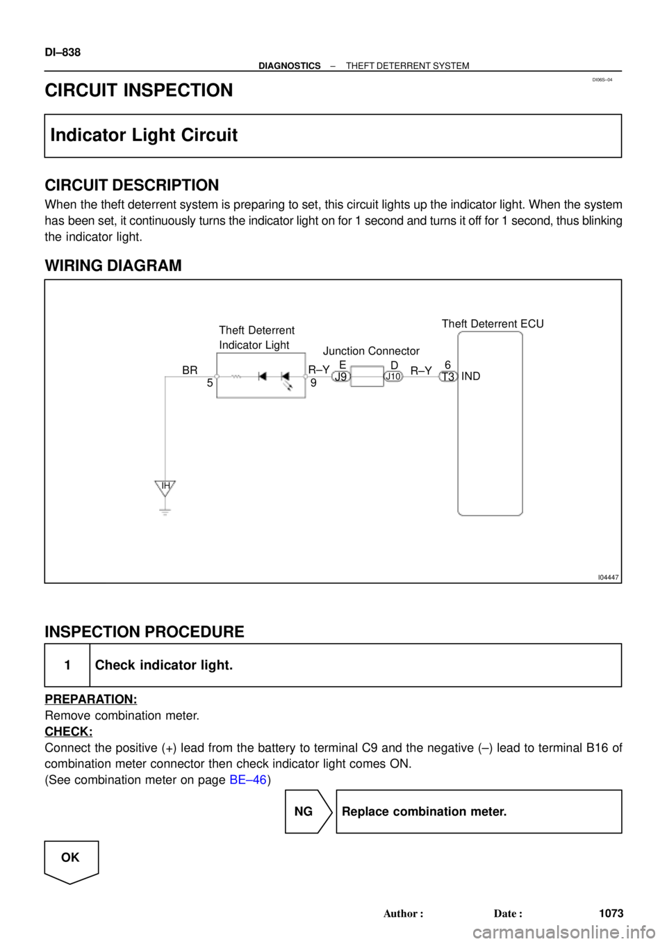
Theft Deterrent ECU
9 Theft Deterrent
Indicator Light
5IND 6
BR
IH
R±Y
T3 R±YE
D
J9J10
Junction Connector
DI±838
± DIAGNOSTICSTHEFT DETERRENT SYSTEM
1073 Author�: Date�:
CIRCUIT INSPECTION
Indicator Light Circuit
CIRCUIT DESCRIPTION
When the theft deterrent system is preparing to set, this circuit lights up the indicator light. When the system
has been set, it continuously turns the indicator light on for 1 second and turns it off for 1 second, thus blinking
the indicator light.
WIRING DIAGRAM
INSPECTION PROCEDURE
1 Check indicator light.
PREPARATION:
Remove combination meter.
CHECK:
Connect the positive (+) lead from the battery to terminal C9 and the negative (±) lead to terminal B16 of
combination meter connector then check indicator light comes ON.
(See combination meter on page BE±46)
NG Replace combination meter.
OK
Page 3260 of 4770
I00238
Theft Deterrent ECU
+B2
E
W±B L±WL±W
J/C
T4
T3
J/C
1G 1
A
AD
8
1W DOME12
R
IF
R
E
T3
+B1
DOOR
J34
C
1B 1D
B±R SHORT PIN
E/G Room J/B No.2
1 4
FL BLOCK
C
R B
F6
F4F9
FL MAIN
Battery
B±G2A1
2J
111
1
7 ALT 1
1
J17 J16
Instrument Panel J/B
Instrument Panel J/B
J5
J/C
R±Y12 DIODE (DOME)
W±B
DI±840
± DIAGNOSTICSTHEFT DETERRENT SYSTEM
1075 Author�: Date�:
ECU Power Source Circuit
CIRCUIT DESCRIPTION
This circuit provides power to operate the theft deterrent ECU.
WIRING DIAGRAM
DI06T±06
Page 3261 of 4770
I00268
I00269
I00275
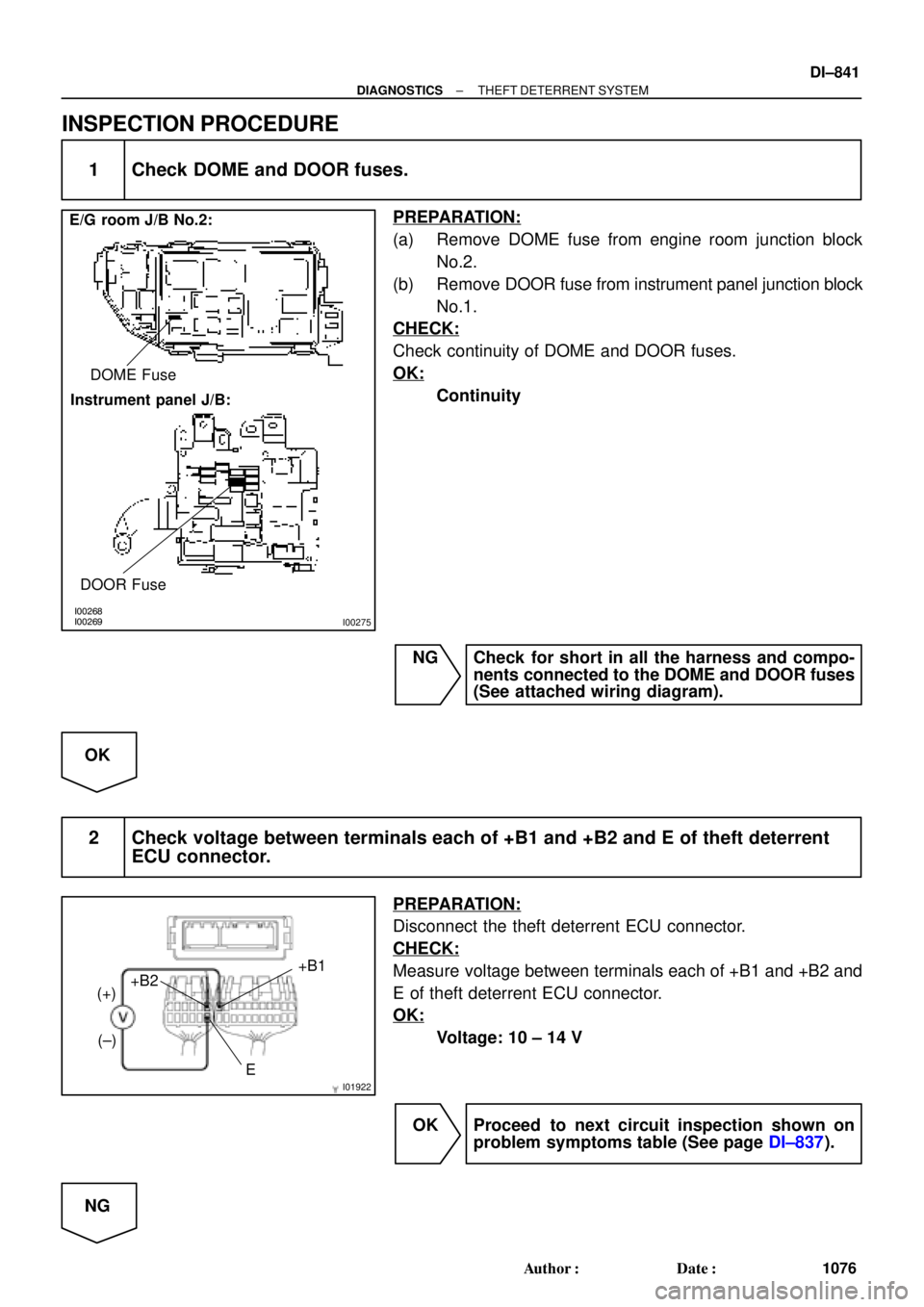
E/G room J/B No.2:
Instrument panel J/B:DOME Fuse
DOOR Fuse
I01922E+B1
+B2
(+)
(±)
± DIAGNOSTICSTHEFT DETERRENT SYSTEM
DI±841
1076 Author�: Date�:
INSPECTION PROCEDURE
1 Check DOME and DOOR fuses.
PREPARATION:
(a) Remove DOME fuse from engine room junction block
No.2.
(b) Remove DOOR fuse from instrument panel junction block
No.1.
CHECK:
Check continuity of DOME and DOOR fuses.
OK:
Continuity
NG Check for short in all the harness and compo-
nents connected to the DOME and DOOR fuses
(See attached wiring diagram).
OK
2 Check voltage between terminals each of +B1 and +B2 and E of theft deterrent
ECU connector.
PREPARATION:
Disconnect the theft deterrent ECU connector.
CHECK:
Measure voltage between terminals each of +B1 and +B2 and
E of theft deterrent ECU connector.
OK:
Voltage: 10 ± 14 V
OK Proceed to next circuit inspection shown on
problem symptoms table (See page DI±837).
NG
Page 3263 of 4770
I00261
Theft Deterrent ECU
SH
T39
W±L IG3
5
W±L IK1
4
W±L
HORN
1 2
W
3
2F
HORN
1
2A
E/G Room J/B No.2
B F6 F4
FL BLOCK
B±G
FL MAIN
Battery1
1
± DIAGNOSTICSTHEFT DETERRENT SYSTEM
DI±843
1078 Author�: Date�:
Theft Deterrent Horn Circuit
CIRCUIT DESCRIPTION
When the theft deterrent system is activated, the relay in the ECU turns ON and OFF cycles of approximately
0.2 sec., causing the theft deterrent horn to blow (See the wiring diagram below).
In this condition, if any of the following operations is done, the relay in the ECU turns OFF, thus stopping
the theft deterrent horn from blowing:
(1) Unlock the front LH or RH door with key.
(2) Turn the ignition switch to ACC or ON position.
(3) Unlock the doors with the wireless door lock control system.
(4) Wait for approximately 60 seconds.
(5) Push the panic switch of the wireless door lock control system.
WIRING DIAGRAM
DI06V±06
Page 3265 of 4770
I00262
Theft Deterrent ECU
HORN
T3
12
G±B IG1
11
G±B
C CJ/C J2
G±B
G±W1
1
Horn
E/G Room J/B No.2
HORN Relay
31
2F
10
2K2 5
1 HORN
12A
B
1
F6
FL BLOCK
1
F4
B±G
FL MAIN
Battery
± DIAGNOSTICSTHEFT DETERRENT SYSTEM
DI±845
1080 Author�: Date�:
Horn Relay Circuit
CIRCUIT DESCRIPTION
When the theft deterrent system is activated, it causes the Tr in the ECU to switch ON and OFF in approxi-
mately 0.4 sec. cycles. This switches the horn relay ON and OFF, thus the horns blow (See the wiring dia-
gram below).
In this condition, if any of the following operations is done, the Tr in the ECU goes off and the horn relay
switches off, thus stopping the horns from blowing:
(1) Unlock the front LH or RH door with key.
(2) Turn the ignition switch to ACC or ON position.
(3) Unlock the doors with the wireless door lock control system.
(4) Wait for approximately 60 seconds.
(5) Push the panic switch of the wireless door lock control system.
WIRING DIAGRAM
DI06W±06