Page 4123 of 4770
SF07K±04
S04505
S04498
S06086
Fuel Hose
Clamp
S05352
± SFI (1MZ±FE)INJECTOR
SF±23
1522 Author�: Date�:
REMOVAL
1. REMOVE AIR CLEANER HOSE
2. REMOVE AIR INTAKE CHAMBER ASSEMBLY
(See page EM±32)
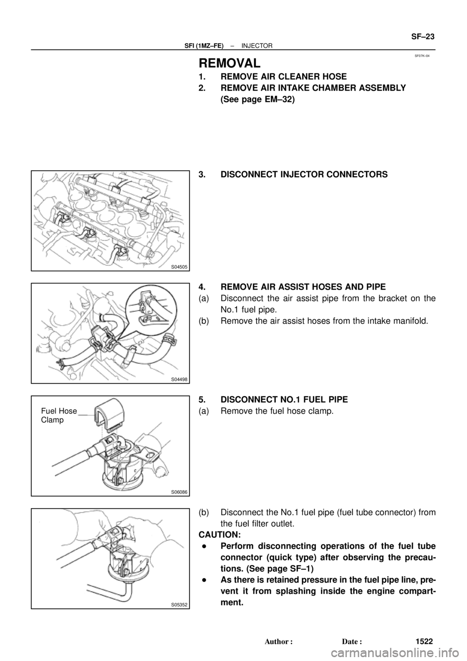
3. DISCONNECT INJECTOR CONNECTORS
4. REMOVE AIR ASSIST HOSES AND PIPE
(a) Disconnect the air assist pipe from the bracket on the
No.1 fuel pipe.
(b) Remove the air assist hoses from the intake manifold.
5. DISCONNECT NO.1 FUEL PIPE
(a) Remove the fuel hose clamp.
(b) Disconnect the No.1 fuel pipe (fuel tube connector) from
the fuel filter outlet.
CAUTION:
�Perform disconnecting operations of the fuel tube
connector (quick type) after observing the precau-
tions. (See page SF±1)
�As there is retained pressure in the fuel pipe line, pre-
vent it from splashing inside the engine compart-
ment.
Page 4126 of 4770
SST (Hose)
O±Ring
SST
(Clamp)
Vinyl Tube
Vinyl Tube
O±Ring
SST (Union)
SST (Hose)
SST
(Clamp)
California A/T
Except California A/T
S05358
TOYOTA
Hand±Held Tester SF±26
± SFI (1M")
B01914
SST (Union)SST (Hose)
O±Ring
SST
(Clamp)
Vinyl Tube
Vinyl Tube
O±Ring
SST (Union)
SST (Hose)
SST
(Clamp)
California A/T
Except California A/T
S05358
TOYOTA
Hand±Held Tester SF±26
± SFI (1MZ±FE)INJECTOR
1525 Author�: Date�:
(c) Install the grommet and O±Ring to the injector.
(d) Connect SST (union and hose) to the injector, and hold
the injector and union with SST (clamp).
SST 09268±41047
(e) Put the injector into a graduated cylinder.
HINT:
Install a suitable vinyl hose onto the injector to prevent gasoline
from splashing out.
(f) Connect a TOYOTA hand±held tester to the DLC3.
(g) Turn the ignition switch ON and push the TOYOTA hand±
held tester main switch ON.
NOTICE:
Do not start the engine.
(h) Select the ACTIVE TEST mode on the TOYOTA hand±
held tester.
(i) Please refer to the TOYOTA hand±held tester operator's
manual for further details.
(j) If you have no TOYOTA hand±held tester, connect the
positive (+) and negative (±) leads from the battery to the
fuel pump connector. (See page SF±6)
Page 4127 of 4770

BatterySST
(Wire)
B00628
California A/TExcept
California A/T
± SFI (1MZ±FE)INJECTOR
SF±27
1526 Author�: Date�:
(k) Connect SST (wire)")
B01913
California A/T
Except California A/TBatterySST
(Wire)
BatterySST
(Wire)
B00628
California A/TExcept
California A/T
± SFI (1MZ±FE)INJECTOR
SF±27
1526 Author�: Date�:
(k) Connect SST (wire) to the injector and battery for 15 se-
conds, and measure the injection volume with a gra-
duated cylinder. Test each injector 2 or 3 times.
SST 09842±30070
Volume:
60 ± 73 cm
3 (3.4 ± 4.5 cu in.) per 15 sec.
Difference between each injector:
13 cm
3 (0.8 cu in.) or less
If the injection volume is not as specified, replace the injector.
2. INSPECT LEAKAGE
(a) In the condition above, disconnect the test probes of SST
(wire) from the battery and check the fuel leakage from
the injector.
SST 09842±30070
Fuel drop: 1 drop or less per 12 minutes
(b) Turn the ignition switch OFF.
(c) Disconnect the negative (±) terminal cable from the bat-
tery.
(d) Remove the SST and fuel tube connector.
SST 09268±41047, 09842±30070
CAUTION:
�Perform disconnecting operations of the fuel tube
connector (quick type) after observing the precau-
tions. (See page SF±1)
�As there is retained pressure in the fuel pipe line, pre-
vent it from splashing inside the engine compart-
ment.
(e) Disconnect the TOYOTA hand±held tester from the
DLC3.
Page 4137 of 4770
THROTTLE BODY
SF±37
1536 Author�: Date�:
THROTTLE BODY
ON±VEHICLE INSPECTION
1. INSPECT THROTTLE BODY
Check th")
S04593
SF07T±03
S04536
Vacuum
VTAOhmmeter
E2
VC
S04604
Plug
Disconnect
± SFI (1MZ±FE)THROTTLE BODY
SF±37
1536 Author�: Date�:
THROTTLE BODY
ON±VEHICLE INSPECTION
1. INSPECT THROTTLE BODY
Check that the throttle linkage moves smoothly.
2. INSPECT THROTTLE POSITION SENSOR
(a) Disconnect the sensor connector.
(b) Disconnect the vacuum hose from the throttle body.
(c) Apply vacuum to the throttle opener.
(d) Using an ohmmeter, measure the resistance between
each terminal.
Resistance:
Throttle valve
conditionBetween
terminalsResistance
Fully closedVTA ± E20.2 ± 6.3 kW
Fully openVTA ± E22.0 ± 10.2 kW
±VC ± E22.5 ± 5.9 kW
(e) Reconnect the vacuum hose to the throttle body.
(f) Reconnect the sensor connector.
3. INSPECT THROTTLE OPENER
(a) Allow the engine to warm up to normal operating tempera-
ture.
(b) Check idle speed.
Idle speed: 700 ± 50 rpm
(c) Disconnect the vacuum hose from the throttle opener,
and plug the hose end.
(d) Check the throttle opener setting speed.
Throttle opener setting speed: 900 ± 1,950 rpm
If the throttle opener setting is not as specified, replace the
throttle body.
(e) Stop the engine.
(f) Reconnect the vacuum hose to the throttle opener.
(g) Start the engine and check that the idle speed returns to
the correct speed.
Page 4139 of 4770
SF07V±03
S04506
S06123
(a)
(b)
(d) (e)
(c)
S04527
EGR Gas Temperature
Sensor Bracket
± SFI (1MZ±FE)THROTTLE BODY
SF±39
1538 Author�: Date�:
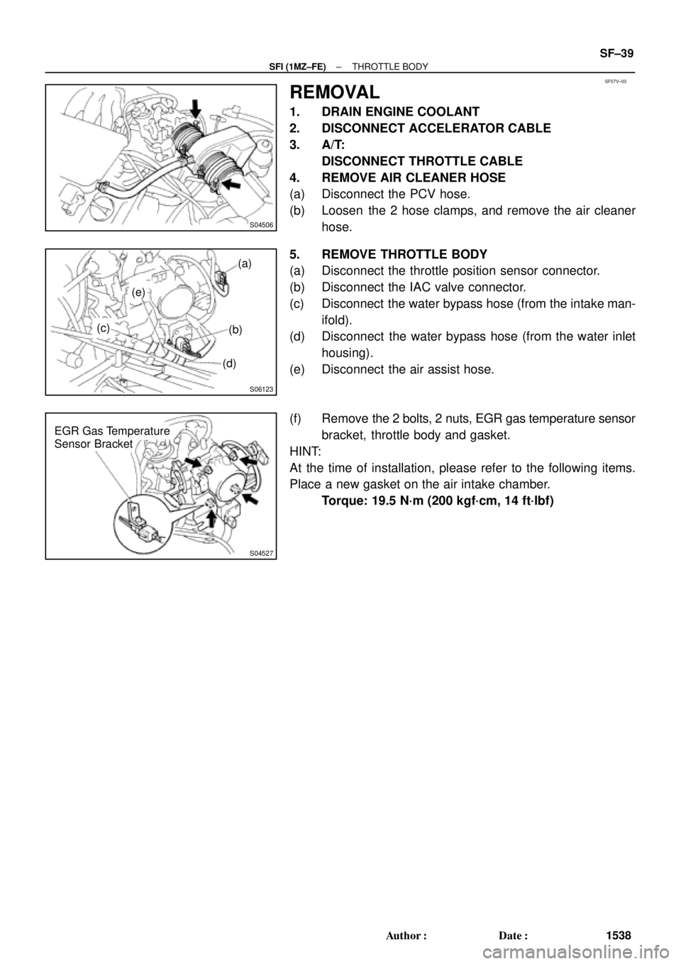
REMOVAL
1. DRAIN ENGINE COOLANT
2. DISCONNECT ACCELERATOR CABLE
3. A/T:
DISCONNECT THROTTLE CABLE
4. REMOVE AIR CLEANER HOSE
(a) Disconnect the PCV hose.
(b) Loosen the 2 hose clamps, and remove the air cleaner
hose.
5. REMOVE THROTTLE BODY
(a) Disconnect the throttle position sensor connector.
(b) Disconnect the IAC valve connector.
(c) Disconnect the water bypass hose (from the intake man-
ifold).
(d) Disconnect the water bypass hose (from the water inlet
housing).
(e) Disconnect the air assist hose.
(f) Remove the 2 bolts, 2 nuts, EGR gas temperature sensor
bracket, throttle body and gasket.
HINT:
At the time of installation, please refer to the following items.
Place a new gasket on the air intake chamber.
Torque: 19.5 N´m (200 kgf´cm, 14 ft´lbf)
Page 4142 of 4770
IDLE AIR CONTROL (IAC) VALVE
1541 Author�: Date�:
IDLE AIR CONTROL (IAC) VALVE
ON±VEHICLE INSPECTION
1. INSPECT")
SF07Y±03
S04529
E1DLC1
SST
TE1
DLC1
S04533
RSC
+B
RSO
Ohmmeter SF±42
± SFI (1MZ±FE)IDLE AIR CONTROL (IAC) VALVE
1541 Author�: Date�:
IDLE AIR CONTROL (IAC) VALVE
ON±VEHICLE INSPECTION
1. INSPECT IAC VALVE OPERATION
(a) Initial conditions:
�Engine at normal operating temperature
�Idle speed checked correctly
�Transmission in neutral position
�A/C switch OFF
(b) Using SST, connect terminals TE1 and E1 of the
DLC1.
SST 09843±18020
(c) After engine speed is kept at approx. 1,000 rpm for 5 se-
conds, check that it returns to idle speed.
If the engine speed operation is not as specified, check the IAC
valve, wiring and ECM.
(d) Remove the SST from the DLC1.
SST 09843±18020
2. INSPECT IAC VALVE RESISTANCE
NOTICE:
ºColdº and ºHotº in the following sentences express the
temperature of the coils themselves. ºColdº is from ±10°C
(14°F) to 50°C (122°F) and ºHotº is from 50°C (122°F) to
100°C (212°F).
(a) Disconnect the IAC valve connector.
(b) Using an ohmmeter, measure the resistance between ter-
minal +B and other terminals (RSC, RSO).
Resistance:
Cold17.0 ± 25.0 W
Hot21.5 ± 29.5 W
If resistance is not as specified, replace the IAC valve.
(c) Reconnect the IAC valve connector.
3. INSPECT AIR ASSIST SYSTEM
(a) Initial conditions:
�Engine at normal operating temperature
�Idle speed checked correctly
�Transmission in neutral position
�A/C switch OFF
Page 4143 of 4770
S04529
E1DLC1
SST
TE1
DLC1
S04531
DisconnectPlug
Plug
± SFI (1MZ±FE)IDLE AIR CONTROL (IAC) VALVE
SF±43
1542 Author�: Date�:
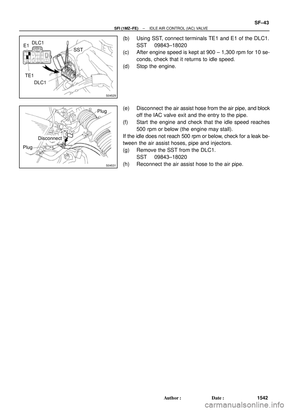
(b) Using SST, connect terminals TE1 and E1 of the DLC1.
SST 09843±18020
(c) After engine speed is kept at 900 ± 1,300 rpm for 10 se-
conds, check that it returns to idle speed.
(d) Stop the engine.
(e) Disconnect the air assist hose from the air pipe, and block
off the IAC valve exit and the entry to the pipe.
(f) Start the engine and check that the idle speed reaches
500 rpm or below (the engine may stall).
If the idle does not reach 500 rpm or below, check for a leak be-
tween the air assist hoses, pipe and injectors.
(g) Remove the SST from the DLC1.
SST 09843±18020
(h) Reconnect the air assist hose to the air pipe.
Page 4148 of 4770
S05036
Vacuum Gage
SF083±03
S05037
Approx.
27.6 kPa SF±48
± SFI (1MZ±FE)ACOUSTIC CONTROL INDUCTION SYSTEM (ACIS)
1547 Author�: Date�:
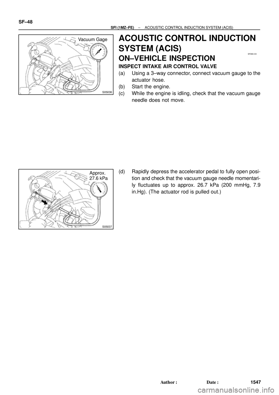
ACOUSTIC CONTROL INDUCTION
SYSTEM (ACIS)
ON±VEHICLE INSPECTION
INSPECT INTAKE AIR CONTROL VALVE
(a) Using a 3±way connector, connect vacuum gauge to the
actuator hose.
(b) Start the engine.
(c) While the engine is idling, check that the vacuum gauge
needle does not move.
(d) Rapidly depress the accelerator pedal to fully open posi-
tion and check that the vacuum gauge needle momentari-
ly fluctuates up to approx. 26.7 kPa (200 mmHg, 7.9
in.Hg). (The actuator rod is pulled out.)