Page 4041 of 4770
GasketSST (Union Bolt)
SST
(Gauge)
Gasket
S04508
Ohmmeter
4
5
± SFI (5S±FE)FUEL PUMP
SF±7
1440 Author�: Date�:
(d) Install the fuel inlet hose and SST (pres")
S05328
Fuel Inlet
Hose
Gasket
SST (Union)GasketSST (Union Bolt)
SST
(Gauge)
Gasket
S04508
Ohmmeter
4
5
± SFI (5S±FE)FUEL PUMP
SF±7
1440 Author�: Date�:
(d) Install the fuel inlet hose and SST (pressure gauge) to the
fuel filter outlet with the 3 gaskets and SST (union bolt).
SST 09268±45014 (09268±41190, 90405±06167)
Torque: 29 N´m (300 kgf´cm, 21 ft´lbf)
(e) Wipe off any splattered gasoline.
(f) Reconnect the negative (±) terminal cable to the battery.
(g) Connect a TOYOTA hand±held tester to the DLC3.
(See step 1 in check fuel pump operation (a) to (e))
(h) Measure the fuel pressure.
Fuel pressure:
301 ± 347 kPa (3.1 ± 3.5 kgf/cm
2, 44 ± 50 psi)
If pressure is high, replace the fuel pressure regulator.
If pressure is low, check the fuel hoses, fuel hose connections,
fuel pump, fuel filter and fuel pressure regulator.
(i) Disconnect the TOYOTA hand±held tester from the
DLC3.
(j) Start the engine.
(k) Measure the fuel pressure at idle.
Fuel pressure:
301 ± 347 kPa (3.1 ± 3.5 kgf/cm
2, 44 ± 50 psi)
(l) Stop the engine.
(m) Check that the fuel pressure remains as specified for 5
minutes after the engine has stopped.
Fuel pressure:
147 kPa (1.5 kgf/cm
2, 21 psi) or more
If pressure is not as specified, check the fuel pump, pressure
regulator and/or injectors.
(n) After checking fuel pressure, disconnect the negative (±)
terminal cable from the battery and carefully remove the
SST to prevent gasoline from splashing.
SST 09268±45014
(o) Reconnect the fuel inlet hose with 2 new gaskets and the
union bolt.
Torque: 29 N´m (300 kgf´cm, 21 ft´lbf)
(p) Reconnect the negative (±) terminal cable to the battery.
(q) Check for fuel leaks. (See page SF±1)
3. REMOVE REAR SEAT CUSHION
4. REMOVE FLOOR SERVICE HOLE COVER
5. DISCONNECT FUEL PUMP & SENDER GAUGE CON-
NECTOR
6. INSPECT FUEL PUMP RESISTANCE
Using an ohmmeter, measure the resistance between terminals
4 and 5.
Resistance: 0.2 ± 3.0 W at 20°C (68°F)
If the resistance is not as specified, replace the fuel pump.
Page 4054 of 4770
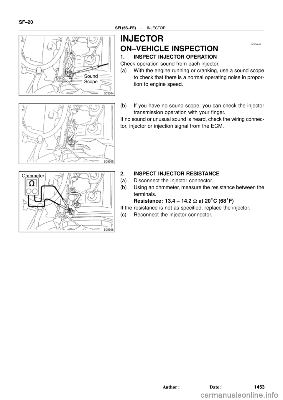
S05304
Sound
Scope
SF0DG±03
S05305
S05306
Ohmmeter SF±20
± SFI (5S±FE)INJECTOR
1453 Author�: Date�:
INJECTOR
ON±VEHICLE INSPECTION
1. INSPECT INJECTOR OPERATION
Check operation sound from each injector.
(a) With the engine running or cranking, use a sound scope
to check that there is a normal operating noise in propor-
tion to engine speed.
(b) If you have no sound scope, you can check the injector
transmission operation with your finger.
If no sound or unusual sound is heard, check the wiring connec-
tor, injector or injection signal from the ECM.
2. INSPECT INJECTOR RESISTANCE
(a) Disconnect the injector connector.
(b) Using an ohmmeter, measure the resistance between the
terminals.
Resistance: 13.4 ± 14.2 W at 20°C (68°F)
If the resistance is not as specified, replace the injector.
(c) Reconnect the injector connector.
Page 4055 of 4770
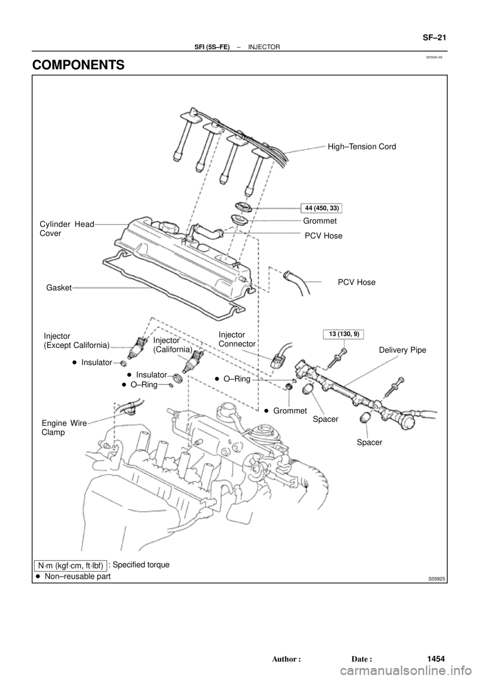
SF0DH±03
N´m (kgf´cm, ft´lbf)
S05925
Cylinder Head
Cover
Gasket
Injector
(Except California)
� Insulator
Engine Wire
ClampHigh±Tension Cord
Grommet
PCV Hose
Delivery Pipe Injector
Connector Injector
(California)
Spacer
Spacer � Insulator
� O±Ring� O±Ring
� Grommet
� Non±reusable part
44 (450, 33)
13 (130, 9)
PCV Hose
: Specified torque
± SFI (5S±FE)INJECTOR
SF±21
1454 Author�: Date�:
COMPONENTS
Page 4056 of 4770

(e)
(d)
B06353
B06354
SF±22
± SFI (5S±FE)INJECTOR
1455 Author�: Date�:
REMOVAL
1. REMOVE CYLINDER HEAD COVER
(a) Disconnect the 4 high±tension cords from the clamps on
the cy")
SF0DI±03
S05289
(c)
(e)
(d)
B06353
B06354
SF±22
± SFI (5S±FE)INJECTOR
1455 Author�: Date�:
REMOVAL
1. REMOVE CYLINDER HEAD COVER
(a) Disconnect the 4 high±tension cords from the clamps on
the cylinder head cover.
(b) Disconnect the 4 high±tension cords from the spark
plugs.
(c) Disconnect the PCV hose from the intake manifold.
(d) Disconnect the PCV hose from the cylinder head cover.
(e) Disconnect the engine wire clamp from the mounting bolt
of the No.2 timing belt cover.
(f) Remove the cylinder head cover. (See page EM±33)
NOTICE:
Cover the cylinder head with a clean cloth to prevent dirt,
etc. getting into the cylinder head.
2. REMOVE DELIVERY PIPE AND INJECTORS
(a) Disconnect the 4 injector connectors.
(b) Remove the 2 bolts holding the delivery pipe to the cylin-
der head.
(c) Disconnect the delivery pipe from the 4 injectors.
(d) Pull out the 4 injectors.
NOTICE:
Be careful not to drop the injectors.
(e) Remove the 4 insulators (Except California) and 2
spacers from the cylinder head.
(f) California:
Remove the 2 O±rings, insulator and grommet from each
injector.
(g) Except California:
Remove the O±ring and grommet from each injector.
Page 4057 of 4770
Union Bolt
SST (Union)
Injector Fuel Filter
(On Vehicle)SST
(Clamp)
SST
(Union)
S05522
S05524
Union Bolt
Gasket SST (Union)
SST (Hose)
P01078
SST
(Clamp) O±Ring
Vinyl
Tube")
SF0DJ±03
S05525
SST (Hose)Union Bolt
SST (Union)
Injector Fuel Filter
(On Vehicle)SST
(Clamp)
SST
(Union)
S05522
S05524
Union Bolt
Gasket SST (Union)
SST (Hose)
P01078
SST
(Clamp) O±Ring
Vinyl
Tube SST (Union)SST (Hose)
S05331
± SFI (5S±FE)INJECTOR
SF±23
1456 Author�: Date�:
INSPECTION
1. INSPECT INJECTOR INJECTION
CAUTION:
Keep injector clean of sparks during the test.
(a) Remove the union bolt and 2 gaskets, and disconnect the
fuel inlet hose from the fuel filter outlet.
(b) Connect SST (union and hose) to the fuel filter outlet with
the 2 gaskets and union bolts.
SST 09268±41047 (90405±09015)
Torque: 29 N´m (300 kgf´cm, 21 ft´lbf)
(c) Install the grommet and O±ring to the injector.
(d) Connect SST (union and hose) to the injector, and hold
the injector and union with SST (clamp).
SST 09268±41047 (09268±41100, 09268±41110)
(e) Put the injector into the graduated cylinder.
CAUTION:
Install a suitable vinyl hose onto the injector to prevent
gasoline from splashing out.
(f) Connect a TOYOTA hand±held tester to the DLC3.
(g) Connect the battery negative (±) cable to the battery.
(h) Turn the ignition switch ON and push the TOYOTA hand±
held tester main switch ON.
NOTICE:
Do not start the engine.
(i) Select the ACTIVE TEST mode on the TOYOTA hand±
held tester.
(j) Please refer to the TOYOTA hand±held tester operator's
manual for further details.
Page 4060 of 4770

(c) (d) SF±26
± SFI (5S±FE)INJECTOR
1459 Author�: Date�:
(h) Attach the 4 injectors and delivery pipe assembly t")
B06352
S05976
Upward
Turn
Connector
B06351
Gray
Brown No.1
No.2
No.3
No.4
S05289
(b)
(c) (d) SF±26
± SFI (5S±FE)INJECTOR
1459 Author�: Date�:
(h) Attach the 4 injectors and delivery pipe assembly to the
cylinder head.
(i) Temporarily install the 2 bolts holding the delivery pipe to
the cylinder head.
(j) Check that the injectors rotate smoothly.
HINT:
If injectors do not rotate smoothly, the probable cause is incor-
rect installation of O±rings. Replace the O±rings.
(k) Position the injector connector upward.
(l) Tighten the 2 bolts holding the delivery pipe to the cylinder
head.
Torque: 13 N´m (130 kgf´cm, 9 ft´lbf)
(m) Connect the 4 injector connectors.
HINT:
The No.1 and No.3 injector connectors are brown, and the No.2
and No.4 injector connectors are gray.
2. INSTALL CYLINDER HEAD COVER
(a) Install the cylinder head cover. (See page EM±53)
(b) Connect the PCV hose to the intake manifold.
(c) Connect the PCV hose to the cylinder head cover.
(d) Install the engine wire clamp to the mounting bolt of the
No.2 timing belt cover.
(e) Connect the 4 high±tension cords to the spark plugs.
(f) Install the 4 high±tension cords to the clamps on the cylin-
der head cover.
3. CHECK FOR FUEL LEAKS (See page SF±1)
Page 4063 of 4770
THROTTLE BODY
SF±29
1462 Author�: Date�:
THROTTLE BODY
ON±VEHICLE INSPECTION
1. INSPECT THROTTLE B")
B01277
Move
SF0DN±03
B00525
P
R
E
B01278
Disconnect
Vacuum
B01282
VTA
E2
VCOhmmeter
± SFI (5S±FE)THROTTLE BODY
SF±29
1462 Author�: Date�:
THROTTLE BODY
ON±VEHICLE INSPECTION
1. INSPECT THROTTLE BODY
(a) Check that the throttle linkage moves smoothly.
(b) Check the vacuum at each port.
�Start the engine.
�Check the vacuum with your finger.
Port nameAt idleOther than idle
Mark EVacuumVacuum
Mark PNo vacuumVacuum
Mark RNo vacuumNo vacuum
2. INSPECT THROTTLE POSITION SENSOR
(a) Disconnect the sensor connector.
(b) Disconnect the vacuum hose from the throttle opener.
(c) Apply vacuum to the throttle opener.
(d) Using an ohmmeter, measure the resistance between
each terminal.
Clearance between
lever and stop screwBetween
terminalsResistance
0 mm (0 in.)VTA ± E20.2 ± 5.7 kW
Throttle valve fully
openVTA ± E22.0 ± 10.2 kW
±VC ± E22.5 ± 5.9 kW
(e) Reconnect the vacuum hose to the throttle opener.
(f) Reconnect the sensor connector.
3. INSPECT THROTTLE OPENER
(a) Allow the engine to warm up to normal operating tempera-
ture.
Page 4064 of 4770
THROTTLE BODY
1463 Author�: Date�:
(b) Connect a TOYOTA hand±held tester or OBDII scan tool.
(1) Remove the fuse cover")
S05331
B01279
Plug
Disconnect
B01280
2.5 mm Hexagon Wrench
SF±30
± SFI (5S±FE)THROTTLE BODY
1463 Author�: Date�:
(b) Connect a TOYOTA hand±held tester or OBDII scan tool.
(1) Remove the fuse cover on the instrument panel.
(2) Connect a TOYOTA hand±held tester or OBDII
scan tool to the DLC3.
(3) Please refer to the TOYOTA hand±held tester or
OBDII scan tool operator's manual for further de-
tails.
(c) Check the idle speed.
Idle speed: 700 ± 50 rpm
(d) Check and adjust the throttle opener setting speed.
(1) Disconnect the vacuum hose from the throttle open-
er, and plug the hose end.
(2) Maintain the engine speed at 2,500 rpm.
(3) Release the throttle valve.
(4) Check that the throttle opener is set.
Throttle opener setting speed:
1,300 ± 1,500 rpm (w/ Cooling fan OFF)
(5) Using a 2.5 mm hexagon wrench, loosen the lock
nut and adjust the throttle opener setting speed by
turning the throttle opener adjusting screw. Tighten
the lock nut.
(6) Reconnect the vacuum hose to the throttle opener.
(e) Disconnect the TOYOTA hand±held tester or OBDII scan
tool.