Page 4066 of 4770
SF0DP±03
B01283
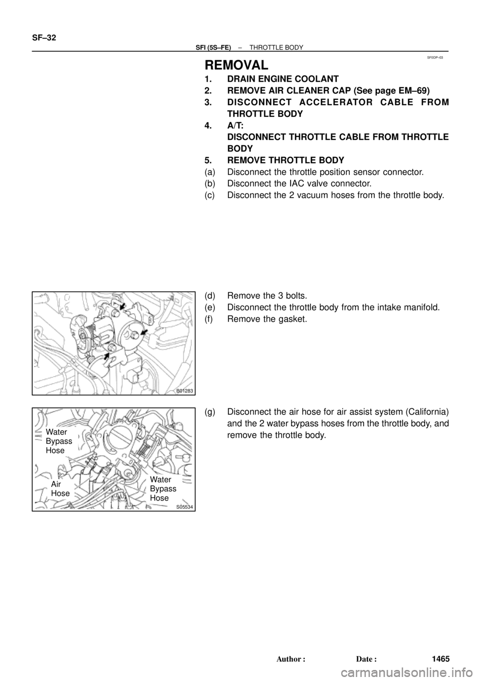
S05534
Water
Bypass
Hose
Water
Bypass
HoseAir
Hose SF±32
± SFI (5S±FE)THROTTLE BODY
1465 Author�: Date�:
REMOVAL
1. DRAIN ENGINE COOLANT
2. REMOVE AIR CLEANER CAP (See page EM±69)
3. DISCONNECT ACCELERATOR CABLE FROM
THROTTLE BODY
4. A/T:
DISCONNECT THROTTLE CABLE FROM THROTTLE
BODY
5. REMOVE THROTTLE BODY
(a) Disconnect the throttle position sensor connector.
(b) Disconnect the IAC valve connector.
(c) Disconnect the 2 vacuum hoses from the throttle body.
(d) Remove the 3 bolts.
(e) Disconnect the throttle body from the intake manifold.
(f) Remove the gasket.
(g) Disconnect the air hose for air assist system (California)
and the 2 water bypass hoses from the throttle body, and
remove the throttle body.
Page 4068 of 4770
SF0DR±03
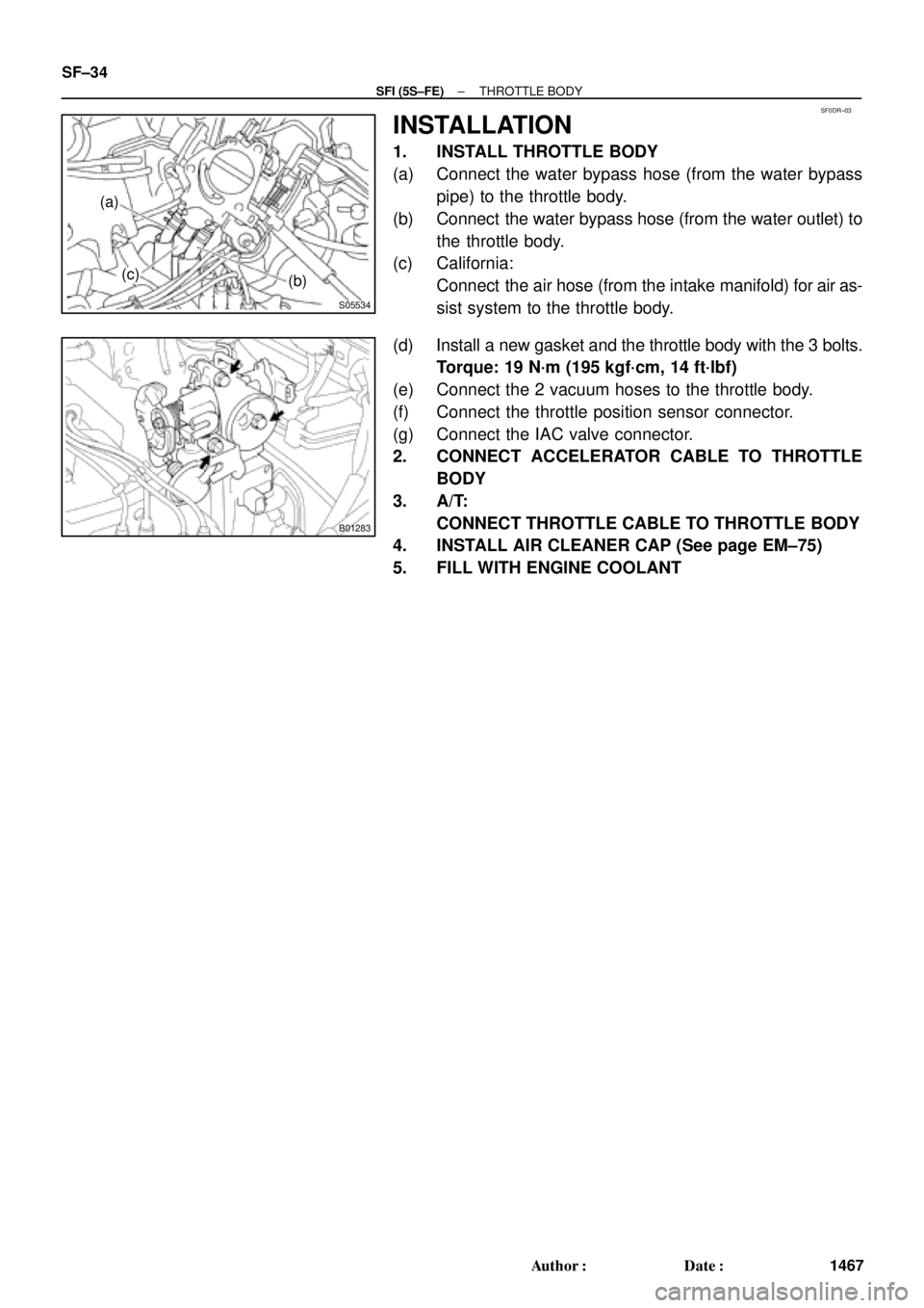
S05534
(a)
(c)
(b)
B01283
SF±34
± SFI (5S±FE)THROTTLE BODY
1467 Author�: Date�:
INSTALLATION
1. INSTALL THROTTLE BODY
(a) Connect the water bypass hose (from the water bypass
pipe) to the throttle body.
(b) Connect the water bypass hose (from the water outlet) to
the throttle body.
(c) California:
Connect the air hose (from the intake manifold) for air as-
sist system to the throttle body.
(d) Install a new gasket and the throttle body with the 3 bolts.
Torque: 19 N´m (195 kgf´cm, 14 ft´lbf)
(e) Connect the 2 vacuum hoses to the throttle body.
(f) Connect the throttle position sensor connector.
(g) Connect the IAC valve connector.
2. CONNECT ACCELERATOR CABLE TO THROTTLE
BODY
3. A/T:
CONNECT THROTTLE CABLE TO THROTTLE BODY
4. INSTALL AIR CLEANER CAP (See page EM±75)
5. FILL WITH ENGINE COOLANT
Page 4069 of 4770
IDLE AIR CONTROL (IAC) VALVE
SF±35
1468 Author�: Date�:
IDLE AIR CONTROL (IAC) VALVE
ON±VEHICLE INSPECTION
1. INSPECT IAC VALVE")
SF0DS±03
A07370
SST
E1
TE1
B01281
Ohmmeter
ISCC+B
ISCO
± SFI (5S±FE)IDLE AIR CONTROL (IAC) VALVE
SF±35
1468 Author�: Date�:
IDLE AIR CONTROL (IAC) VALVE
ON±VEHICLE INSPECTION
1. INSPECT IAC VALVE OPERATION
(a) Initial conditions:
�Engine at normal operating temperature
�Idle speed set correctly
�Transmission in neutral position
(b) Using SST, connect terminals TE1 and E1 of the DLC1.
SST 09843±18020
(c) After the engine speed is kept at 900 ± 1,300 rpm for 5 se-
conds, check that it returns to idle speed.
If the engine speed operation is not as specified, check the IAC
valve, wiring and ECM.
(d) Remove the SST from the DLC1.
SST 09843±18020
2. INSPECT IAC VALVE RESISTANCE
NOTICE:
ºColdº and ºHotº in these sentences express the tempera-
ture of the coils themselves. ºColdº is from ±10°C (14°F) to
50°C (122°F) and ºHotº is from 50°C (122°F) to 100°C
(212°F).
(a) Disconnect the IAC valve connector.
(b) Using an ohmmeter, measure the resistance between ter-
minal +B and other terminals (ISCC, ISCO).
Resistance:
Cold17.0 ± 24.5 W
Hot21.5 ± 28.5 W
If the resistance is not as specified, replace the IAC valve.
(c) Reconnect the IAC valve connector.
Page 4082 of 4770
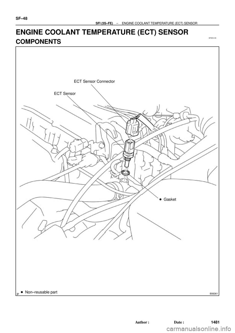
SF0E5±03
B06361
ECT Sensor Connector
ECT Sensor
� Gasket
� Non±reusable part
SF±48
± SFI (5S±FE)ENGINE COOLANT TEMPERATURE (ECT) SENSOR
1481 Author�: Date�:
ENGINE COOLANT TEMPERATURE (ECT) SENSOR
COMPONENTS
Page 4083 of 4770
SF0E6±03
S01196S01699Z17274
Ohmmeter
Resistance kW
Temperature °C (°F) Acceptable 30
20
10
5
3
2
1
0.5
0.3
0.2
0.1
40 ±20 0 20 60 80 100
(212) (176) (140) (104) (68) (32) (±4)
± SFI (5S±FE)ENGINE COOLANT TEMPERATURE (ECT) SENSOR
SF±49
1482 Author�: Date�:
INSPECTION
1. DRAIN ENGINE COOLANT
2. REMOVE ECT SENSOR
3. INSPECT ECT SENSOR
Using an ohmmeter, measure the resistance between the ter-
minals.
Resistance: Refer to the graph
If the resistance is not as specified, replace the ECT sensor.
4. REINSTALL ECT SENSOR
5. REFILL WITH ENGINE COOLANT
Page 4098 of 4770
SF0EL±03
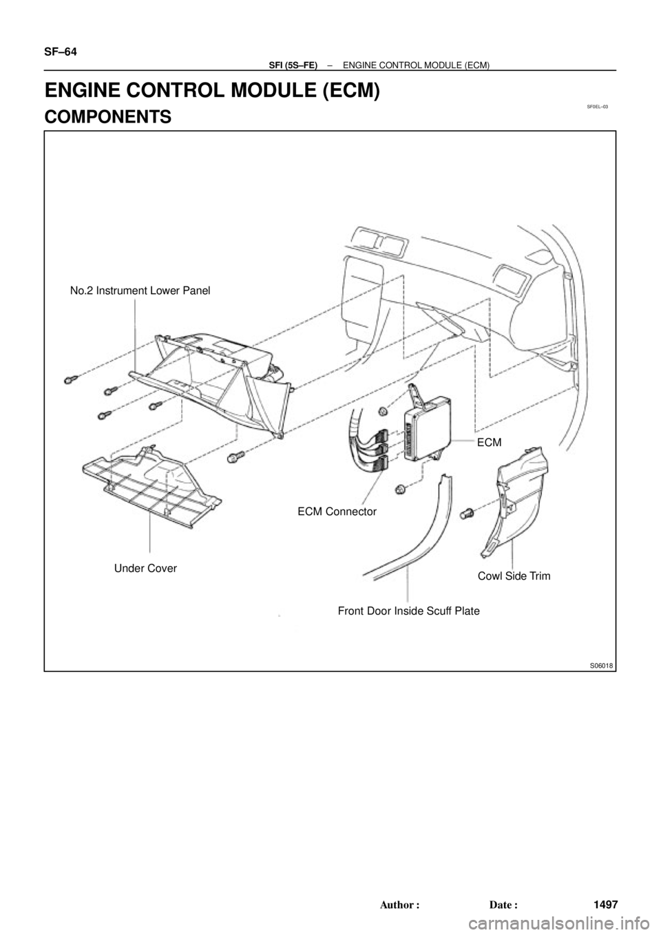
S06018
No.2 Instrument Lower Panel
Under CoverECM ConnectorECM
Cowl Side Trim
Front Door Inside Scuff Plate SF±64
± SFI (5S±FE)ENGINE CONTROL MODULE (ECM)
1497 Author�: Date�:
ENGINE CONTROL MODULE (ECM)
COMPONENTS
Page 4099 of 4770
SF0EM±03
± SFI (5S±FE)ENGINE CONTROL MODULE (ECM)
SF±65
1498 Author�: Date�:
INSPECTION
1. REMOVE ECM
2. INSPECT ECM (See page DI±22)
3. REINSTALL ECM
Page 4100 of 4770
SF0EN±03
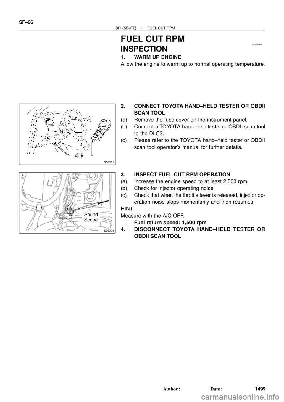
S05331
S05304
Sound
Scope SF±66
± SFI (5S±FE)FUEL CUT RPM
1499 Author�: Date�:
FUEL CUT RPM
INSPECTION
1. WARM UP ENGINE
Allow the engine to warm up to normal operating temperature.
2. CONNECT TOYOTA HAND±HELD TESTER OR OBDII
SCAN TOOL
(a) Remove the fuse cover on the instrument panel.
(b) Connect a TOYOTA hand±held tester or OBDII scan tool
to the DLC3.
(c) Please refer to the TOYOTA hand±held tester or OBDII
scan tool operator's manual for further details.
3. INSPECT FUEL CUT RPM OPERATION
(a) Increase the engine speed to at least 2,500 rpm.
(b) Check for injector operating noise.
(c) Check that when the throttle lever is released, injector op-
eration noise stops momentarily and then resumes.
HINT:
Measure with the A/C OFF.
Fuel return speed: 1,500 rpm
4. DISCONNECT TOYOTA HAND±HELD TESTER OR
OBDII SCAN TOOL
 Acceptable 30
20
10
5
3
2
1
0.5
0.3
0.2
0.1
40 ±20 0 20 60 80 100
(212) (176) (140) (104) (68) (32) (±4)
± SFI (5S±FE)ENGI")